


62-0135
8
Q7300A,C,D,G SERIES 2000 COMMERCIAL THERMOSTAT SUBBASES
Home and Building Control
Honeywell Limited-Honeywell Limitée
155 Gordon Baker Road
North York, Ontario
M2H 2C9
62-0135 J.H. Rev. 12-96
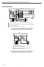
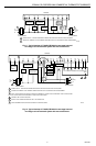
Fig. 17. Typical hookup of T7300D,F/Q7300G in three-stage heat and three-stage cool conventional system.
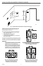
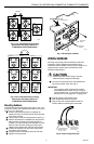
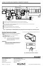
Mounting Thermostat on Subbase
Mount the thermostat on the subbase after the subbase is
installed.
³ Engage tabs at the top of the thermostat and
subbase. Fig. 18.
· Press lower edge of case to latch.
NOTE: To remove the thermostat from the wall,
first pull out at the bottom of the thermo-
stat; then remove the top.
IMPORTANT
Refer to the thermostat installation instructions for
Installer Setup, Settings, Installer Self-Test and
Troubleshooting information.
Fig. 18 Mounting thermostat on subbase.
M4824A
B.
PRESS LOWER EDGE OF CASE TO LATCH.
A.
ENGAGE TABS AT TOP OF THERMOSTAT AND SUBBASE OR WALLPLATE.
Home and Building Control
Honeywell Inc.
Honeywell Plaza
P.O. Box 524
Minneapolis, MN 55408-0524
POWER SUPPLY. PROVIDE DISCONNECT MEANS AND OVERLOAD PROTECTION AS REQUIRED.
JUMPER RC TERMINAL TO RH TERMINAL WHEN INSTALLED ON A SYSTEM WITH ONE TRANSFORMER.
USE A1 AND A2 WHEN THE CONTACTS SHOULD BE NORMALLY CLOSED IN OCCUPIED MODE. USE A2 AND A3 WHEN CONTACTS
SHOULD BE NORMALLY OPEN IN OCCUPIED MODE.
CONNECT GND TO EARTH GROUND.
INSTALL FIELD JUMPER BETWEEN X4 AND X TO POWER LEDS.
USE ECONOMIZER INSTRUCTIONS FOR INSTALLATION DIRECTIONS.
1
1
1
4
6
M4949A
2
2
3
4
5
6
3
5
HEAT
RELAY 3
W2
L1
(HOT)
L2
FAN
RELAY
Y1 G X
SUBBASE
RC RH
C1 T
T7147 REMOTE COMFORT ADJUST MODULE
GND
W1
C2
L1
(HOT)
L2
COMPRESSOR
CONTACTOR 1
C4 C3C5
CA1
T
CA2
CA4 CA3CA5
T
T
Y2
COMPRESSOR
CONTACTOR 2
HEATING
TRANSFORMER
COOLING
TRANSFORMER
W3Y3
HEAT
RELAY 2
COMPRESSOR
CONTACTOR 3
A2 A3A1X3 X1X4
EQUIPMENT
MONITOR 2
EQUIPMENT
MONITOR 1
ECONOMIZER
AS AS
DISCHARGE
AIR
SENSOR
HEAT
RELAY 1
www.honeywell.com/building/components