


69-0638—1 2
Installation
WHEN INSTALLING THIS PRODUCT…
1. Read these instructions carefully. Failure to follow
them could cause a hazardous condition.
2. Installer must be a trained experienced service technician.
3. After installation is complete, check out product op-
eration as provided in these instructions.
IMPORTANT: An incorrectly leveled subbase will cause
the temperature control to deviate from setpoint. It is
not a calibration problem.
CAUTION
1. Disconnect power supply to prevent electrical
shock or equipment damage.
2. To prevent interference with the thermostat
linkage, keep wire length to a minimum and run
wires as close as possible to the subbase.
3. Do not overtighten thermostat captive mount-
ing screws because damage to subbase threads
can result.
4. Do not short across coil terminals on relay. This
can burn out the thermostat heat anticipator.
LOCATION
Locate thermostat about 5 ft [1.5m] above the floor in an
area with good air circulation at average temperature.
Do not mount the thermostat where it may be affected by:
—drafts, or dead spots behind doors and in corners.
—hot or cold air from ducts.
—radiant heat from the sun or appliances.
—concealed pipes and chimneys.
—unheated (uncooled) areas such as an outside wall
behind the thermostat.
Run wires from the heating, cooling or heating/cooling
equipment to the new thermostat location.
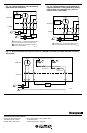
Refer to the Typical Wiring Diagrams section to deter-
mine the number of wires required for your application.
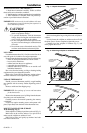
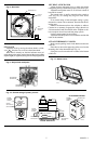
UNPACK THERMOSTAT
Handle your new thermostat carefully; rough handling
may interfere with its accuracy. Before unpacking, refer to
Fig. 1.
Remove and discard the shipping wrap.
IMPORTANT: Save package of screws and instructions
for the homeowner.
Remove the thermostat cover by lifting from the bottom.
Set aside cover until needed later.
Carefully remove the material protecting the mercury
switch bulb.
Loosen two captive mounting screws and separate wall-
plate (if provided) from the back of the thermostat base.
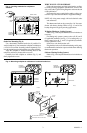
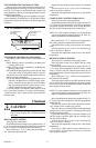
MOUNT WALLPLATE OR SUBBASE
Wall Mounting (Fig. 2)
Hold wallplate or subbase in position on the wall (Fig. 2).
Mark holes on the wall for anchors. Use spirit level to
make sure the wallplate or subbase is level.
Drill 3/16-in. holes, and gently tap anchors into holes
until flush with the wall.
Fig. 1—Unpack thermostat.
12
6
3
9
50
60
70
80
THERMOSTAT
COVER
LIFT
COVER
CAPTIVE
MOUNTING
SCREWS
THERMOSTAT
BASE
M1518
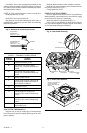
Pull wires through the large wiring hole in the wallplate or
subbase.
Loosely fasten the wallplate or subbase to the wall with
the three screws. Do not completely tighten the screws.
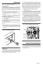
Carefully level the wallplate or subbase (Fig. 3), and
firmly tighten the screws.
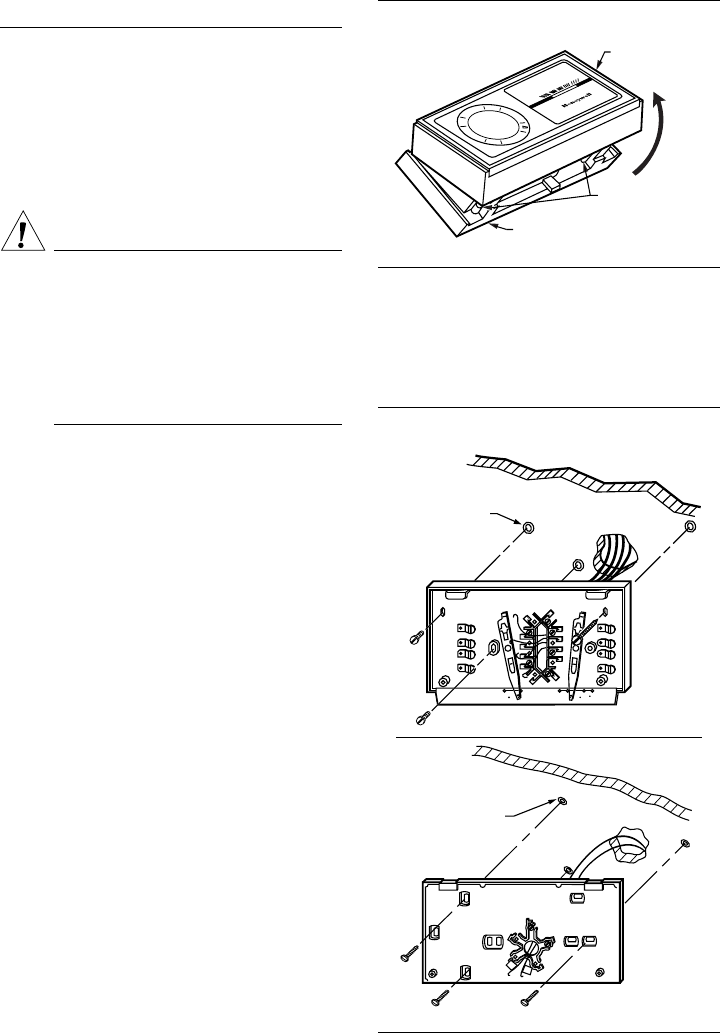
Fig. 2—Mounting wallplate or subbase to wall.
M1552A
AUTO OFF
COOL
HEATON
FAN
R
G
O
W
Y
B
3 SCREW HOLES
WITH PLASTIC
ANCHORS
HEATING/COOLING SUBBASE
3 SCREW HOLES
WITH PLASTIC
ANCHORS
WALLPLATE
M1815