


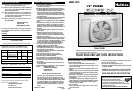


OPERATING INSTRUCTIONS:
• Make sure rotary switch is in the OFF position (see fig. 4).
• Plug into 120V AC electric outlet.
• Turn the Thermostat Dial clockwise toward “LO”.
• Flip the INTAKE/EXHAUST Switch to the desired setting before turning
on the fan. Note: When changing from intake to exhaust we recom-
mend shutting the fan off before switching the intake/exhaust control.
• To start the unit, turn the rotary speed control switch to desired speed
(HI, MED, LO)
NOTE: On the speed control switch: High= the 3 vertical lines, Med= 2
vertical lines & L0 = one vertical line.
Warning: Be sure fan is secure in window at all times. NEVER push or lean
on your fan.
THERMOSTAT INSTRUCTIONS:
Your window fan is equipped with a Comfort Control Thermostat that
automatically turns the fan ON and OFF depending on the preset com-
fort level. This is ideal for operation at night when the temperature
drops.
• While the Window Fan is on, turn the "Comfort Control” Thermostat
dial counter-clockwise towards “HI” until the fan stops. This is the
selected comfort level.
• If the fan is stopped and you want the room cooler, rotate the Comfort
Control Thermostat dial clockwise until the fan starts, towards “LO”
(Towards Cooler).
IMPORTANT: If you desire continuous running of the fan, the Comfort
Control Thermostat dial should be turned all the way clockwise, towards “LO”.
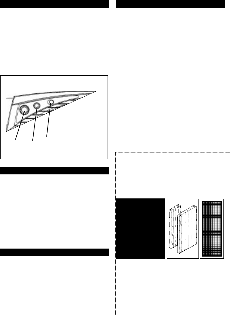
OPTIONAL POLLEN CATCHER INSTRUCTIONS:
The HAWF-1013 can be used with a specially designed air filter. The new
“Pollen Catcher” System will trap small dirt, dust, pollen and other small
particles. Pollen Catcher filters are made of a washable foam material that
can be re-used; with a recommended replacement interval of 2-3 months.
A special limited offer is available on the purchase of Pollen Catcher
Filters. For $12.99 including shipping and handling we will ship you two
filters and a re-usable frame. To reorder call 1-800-5-HOLMES.
CLEANING/MAINTENANCE INSTRUCTIONS:
Follow these instructions to correctly and safely care for your Holmes®
window fan.
Please remember:
• Always unplug the fan before cleaning or disassembling.
• Do not allow water to enter into the fan housing.
• Be sure to use a soft cloth moistened with mild soap solution.
• Do not use any of the following as a cleaner: gasoline, thinner, benzine.
PRE-INSTALLATION INSTRUCTIONS:
Carefully unpack all contents of carton.
• This window fan comes fully assembled and is ready for immediate
installation.
• PLEASE NOTE: There are separate sets of extender panels at each
end of the box, packed in the styrofoam. For this model there are a
total of two, measuring 3.5” each.
• Before installation, familiarize yourself with the built-in side exten-
der (B) and the 2 additional extenders (A) provided to assist you in
achieving the perfect fit for your window fan (see figure #1).
WE RECOMMEND KEEPING THE WINDOW SCREEN IN PLACE.
A. SLIDE-ON EXTENDERS (TWO 3.5”)
B. BUILT-IN SLIDE-OUT EXTENDER (PULLS OUT 7”) not shown
C. 3 SPEED CONTROL
D. THERMOSTAT CONTROL DIAL
E. INTAKE/EXHAUST SWITCH
INSTALLATION INSTRUCTIONS:
This window fan has been designed to fit double-hung or vertical
slider/windows with minimum openings of 19” wide and 14” high. As
noted above, it is also designed and recommended for use with your
window screen in place.
FOR DOUBLE-HUNG AND SLIDER WINDOWS:
NOTE: On SLIDER WINDOWS the bottom section must be the side you
add extenders to (left side). The controls should face toward the window.
STEP 1. With the window open, take an accurate measurement of the
opening where the unit will be placed.
STEP 2. Match your window measurement with the installation guide on
page 2; adding the appropriate extender panel(s) (3.5” each)
to the left side, while using the built-in extender on the right
side (up to 7”).
STEP 3. Once you have added extender panels (if necessary), set the
fan in the window and complete the installation process with the
built-in extender. Pull out both clips on the right side (top to
bottom) of the fan, then adjust the built-in extender to fill the
remaining space. After obtaining a snug, safe fit, lock the
extender in place, by pushing the clips down.
STEP 4. Carefully close the window onto the top of the fan so that the
bottom edge of
the window rests
behind the top
line of the fan
housing. This
helps hold the
fan in place.
CASEMENT WINDOWS:
For a safe, secure fit in your casement window, you will need a special
bracket system. For easier installation in a casement window, we will
provide you with two brackets and screws at no additional cost. Please
keep in mind, your casement window must to be at least 19” high and
14” wide to use this window fan. Please call our customer service
department, 1-800-5-HOLMES, for further assistance.
INSTALLATION GUIDE:
For 19” to 22” Use up to 3” of right side, pull out extender.
For 23” to 26” Use one 3.5” extender panel on the left side. Adjust the
pull out extender on the right for a tight fit (from .5” to 7”)
For 27” to 33” Use two 3.5” extender panels on the left side. Adjust the
pull out extenders on the right for a tight fit (To 7”)
Larger than 33” Additional extender panels will be required.
(See attached mail order offer or call 1-800-5-Holmes.)
DETACH FROM INSTRUCTIONS AND MAIL IN THIS FORM
Fill out form on reverse side or call
1-800-5-HOLMES
to place your order today.
IT'S A GREAT IDEA!
Additional Extender Panels &
Pollen Catcher
™
Filters Available
EXTENDER PANELS
$9.99 (per pair)
POLLEN
CATCHER
™
FILTERS
$12.99 (per pair)
INCLUDES SHIPPING
AND HANDLING
TOP LINE OF FAN
A. 3 SPEED CONTROL
B. THERMOSTAT CONTROL DIAL
C. INTAKE/EXHAUST SWITCH
(Figure 1)
Page2 Page 3
A
C
B
C
A
B
D
E
INSET OF CONTROL PANEL
22”
LEFT
EXTRA EXTENDER PANELS
RIGHT
BUILT-IN, PULL OUT EXTENDERS
Two 3.5” extenders, (Included in your box packed at both ends)
UNIT’S LENGTH
(Figure 3)
(Figure 2)
CLOSE-UP OF CONTROL PANEL
(Figure 4)
PULLS OUT UP TO 7”