


PLEASE READ AND SAVE
THESE IMPORTANT
SAFETY INSTRUCTIONS
When using electrical appliances, basic safety precautions
should always be followed to reduce the risk of fire, electric
shock, and injury to persons, including the following:
1) Read all instructions before using the appliance.
2) To avoid fire or shock hazard, plug the appliance
directly into a 120V AC electrical outlet.
3) Keep the cord out of heavy traffic areas. DO NOT let
the cord hang over the edge of a table or counter.
To avoid fire hazard, NEVER put the cord under rugs,
near heat registers, radiator, stoves, or heaters.
4) To protect against electrical hazards, DO NOT immerse
in water or other liquids. Do not use near water.
5) Close supervision is necessary when any appliance is
used by or near children, or by disabled people.
6) Always unplug the fan before moving it, putting on or
taking off parts, cleaning, or whenever the fan is not
in use. Be sure to pull by the plug and not the cord.
7) Avoid contact with moving parts. DO NOT operate
without fan grills properly in place.
8) DO NOT operate any appliance with a damaged cord
or plug, if motor fan fails to rotate, after the appliance
malfunctions, or if it has been dropped or damaged in
any manner. Return appliance to manufacturer for
examination, electrical or mechanical adjustment, or
repair.
9) DO NOT operate in the presence of explosive and/or
flammable fumes.
10) Use appliance only for intended household use as
described in this manual. Any other use not
recommended by the manufacturer may cause fire,
electric shock, or injury to persons. The use of
attachments not recommended or sold by The
Holmes Group may cause hazards.
11) DO NOT use outdoors.
12) Always use on a dry, level surface.
13) Keep unit away from heated surfaces and open
flames.
14) WARNING: To reduce the risk of fire or electric shock,
DO NOT use this fan with any solid-state speed control
device.
15) DO NOT attempt to repair or adjust any electrical or
mechanical functions on this unit. Doing so will
void your warranty. The inside of the unit contains
no user serviceable parts. All servicing should be
performed by qualified personnel only.
PLEASE READ AND SAVE
THESE IMPORTANT
SAFETY INSTRUCTIONS
ASSEMBLY INSTRUCTIONS:
Base Assembly:
You will need the base and four extension legs.
Push in the small tab on each extension and snap into base.
Pole Assembly:
You will need the completed base and extension pole.
STEP 1: Remove the base collar from the base by turning
counterclockwise.
STEP 2: Take the extension pole, with the solid end down,
and insert it into the base. The hollow end of the
pole (with the screw hole) will be facing up.
STEP 3: PReplace the base collar over the extension pole,
slide it down the pole, and secure it to the base by
turning clockwise.
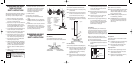
Fan Head Assembly:
You are now ready to assemble the fan head (See Figure #1)
Step 1: Position the rear grill over the motor shaft, making
certain the 2 notches at the top and bottom of the
rear grill fit over the 2 prongs on the motor hous-
ing. Please make sure the rear grill fits securely
against the motor housing.
Step 2: Secure the rear grill in its place using the rear grill
mounting nut. Turn this nut clockwise and tighten
firmly.
Step 3: Slide the fan blade, with the hollowed interior of
the blade facing towards the rear grill firmly onto
the motor shaft. Make sure the shaft protrudes
from the front of the blade.
Step 4: Secure fan blade onto the motor shaft by turning
the blade cap in a counter-clockwise direction until
it is firmly in place.
Step 5: Prepare the front grill by simply snapping the
circular front grill logo plate in place.
Step 6: Center the front grill by aligning the Holmes logo
so it is horizontal and parallel to the floor. Then
secure the front and rear grills completely together
by snapping into place. Lastly, tighten the grill
screw at the bottom of the rear grill.
Final Assembly:
First, place fan head assembly onto the extension pole,
lining up the fan post screw with the hole in the extension
pole. Then, simply insert the fan post screw into the hole
and tighten until a secure fit is obtained. Lastly, insert the
tilt adjustment knob into the neck joint and tighten in place.
NOTE: If your fan does not have a screw hole in the
extension pole but instead has an indentation around the
top of the pole; please do the following:
Step 1: First, place the fan head assembly onto the extension
pole and tighten the fan post screw until a secure fit is
obtained.
Step 2: Insert the tilt adjustment knob into the neck joint
and tighten in place.
OPERATING INSTRUCTIONS:
STEP 1: Set fan on a dry, level surface.
STEP 2: Plug cord into any standard 120V AC outlet. Please
make sure the selector (speed) control is in the
OFF position. Selector (speed) control is located on
the top of the fan motor housing.
STEP 3: The SPEED is adjusted by turning the control knob
to the desired setting, Off-Hi-Med-Lo.
STEP 4: The OSCILLATION control knob is located on the
top of the fan motor housing. To start oscillation,
push control knob down. To stop oscillation, pull
control knob up.
ADJUSTMENT INSTRUCTIONS:
Tilt Adjustment:
Follow these instructions to tilt the Fan Head for upward
angle air movement.
Step 1: To change the tilting angle of the fan head, simply
loosen the Tilt Adjustment Knob (see fig.1).
Step 2: Move the fan head to the desired angle, then
firmly tighten the knob to lock in place.
Height Adjustment:
Follow these instructions to adjust the height of the fan.
Step 1: Turn the extension pole base collar (see figure 3)
counter-clockwise to loosen pole.
Step 2: Adjust the pole to the desired height, and firmly
tighten collar in a clockwise direction.
Base
Collar
Extension
Pole
Base
Figure 2
Figure 3
Fan Post Screw
Extension Pole
Screw Hole
Figure 4
A. LOGO PLATE (SNAP ON)
B. FRONT GRILL
C. BLADE CAP
D. FAN BLADE
E. REAR GRILL
MOUNTING RING
F. PLASTIC BAND
G. GRILL SCREW
H. REAR GRILL
I. MOTOR SHAFT
J. GILL MOUNT
K. SPEED CONTROL KNOB
L. OSCILLATION KNOB
M. MOTOR HOUSING
N. TILT JOINT
O. TILT ADJUSTMENT KNOB
P. F AN POST SCREW
Q. EXTENSION POLE
R. BASE COLLAR
S. BASE
T. FOOT EXTENSIONS (4)
A
N
B
C
D
E
F
G
H
I
M
Figure 1
L
J
K
O
P
Q
R
S
T
THIS PRODUCT IS EQUIPPED WITH A POLARIZED AC
(Alternating Current) PLUG (a plug having one blade
wider than the other). This plug will fit into the power
outlet only one way. If the plug does not fit fully into the
outlet, reverse the plug. If it still does not fit, contact
qualified personnel to install the proper outlet.
DO NOT DEFEAT THE SAFETY PURPOSE OF THIS
POLARIZED PLUG IN ANY WAY
HASF200901UM1.qxd 1/2/02 4:56 PM Page 2