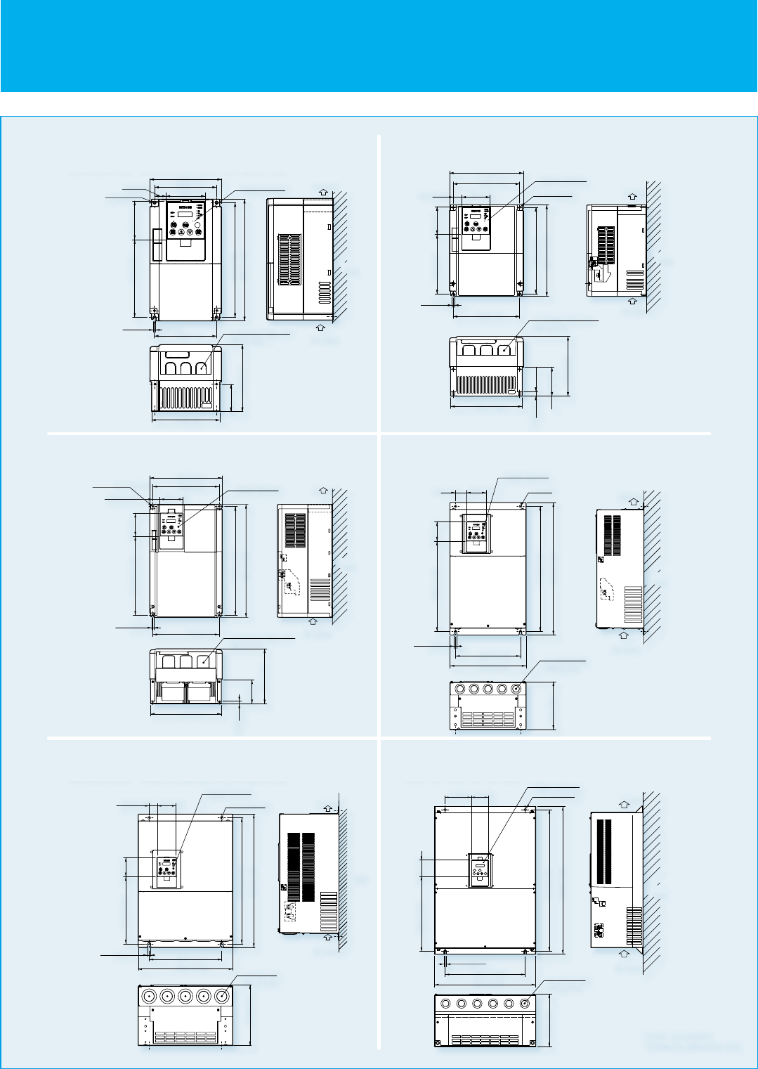
DIMENSIONS
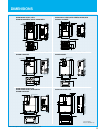
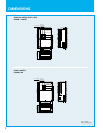
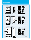
SJ700-004037 LFUF2, LFF2
SJ700-007040HFEF2, HFUF2, 007037HFF2
SJ700-150220 LFUF2,LFF2 /HFEF2, HFUF2,HFF2
SJ700B-185300HFF
SJ700-370450 LFUF2,LFF2
SJ700-370550 HFEF2, HFUF2,HFF2
SJ700B-450750HFF
SJ700-300 LFUF2,LFF2 /HFEF2, HFUF2, HFF2
SJ700B-370HFF
SJ700-550 LFUF2,LFF2
SJ700-055110 LFUF2,LFF2 /HFEF2, HFUF2,HFF2
SJ700B-110150HFF
[Unit: mm(inch)]
Inches for reference only.
7
8
SPECIFICATIONS
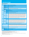
General Specifications
Items
Control
Input signal
Output signal
Monitoring on display
Other functions
Frequency
setting
Operator
External signal*8
External port
Forward /reverse
Start /stop
Operator
External signal
External port Setting via RS485 communication
Terminals
Intelligent
input terminals
8 terminals, NO/NC switchable, sink logic/source logic switchable
Functions
1 terminal (PTC characteristics)Thermistor input
Control method
Output frequency range (*6)
Frequency accuracy
Frequency resolution
Line to line sine wave pulse-width modulation (PWM) control
0.1-400.0Hz(400kW:0.1-120Hz)
Digital: ±0.01% of the maximum frequency, Analog: ±0.2%(25±10˚C)
Digital setting: 0.01Hz, Analog setting: (Maximum frequency)/4,000 (O terminal: 12bit 0-10V, O2 terminal: 12bit -10-+10V)
V/f optionally variable (30-400Hz of base frequency), V/f control (constant torque, reduced torque), Sensorless vector control, 0Hz domain sensorless vector
control, vector control (SJ-FB card option)
SJ700 (Sensorless vector control): 200% at 0.3Hz/ 75kW to 150kW:180% at 0.3Hz,185kW and over:150% at 0.3Hz.
SJ700B (Sensorless vector control): 150% at 0.5Hz/ 90kW and over:120% at 0.5Hz,
SJ700 (0Hz domain with motor one frame size down):150% at around 0Hz/ 75kW and over: 130% at around 0Hz.
±0.5% (sensorless vector control)
0.01-3,600sec. (Linear/curve, accel./decel. selection), Two-stage accel./decel.
SJ700: 0.5-15.0kHz(185kW and over:0.5-3.0kHz)/SJ700B: 0.5-12.0kHz(90kW and over:0.5-8.0kHz)
Performs at start: under set frequency at deceleration, via an external input (braking force, time, and operating frequency).
Up and Down keys
DC 0-10V, -10-+10V (input impedance 10kΩ), 4-20mA (input impedance 100Ω)
Setting via RS485 communication
Start/stop commands (forward/reverse switching by parameter setting)
General Specifications
Forward-operation start/stop commands (reverse-operation start/stop possible when relevant commands are assigned to intelligent input terminals)3-wire
input possible (when relevant commands are assigned to control circuit terminals)
Reverse operation (RV), Multi-speed 1 setting (CF1), Multi-speed 2 setting (CF2), Multi-speed 3 setting (CF3), Multi-speed 4 setting (CF4), Jogging (JG),
external DC braking (DB), 2nd motor control (SET), 2-stage acceleration/deceleration (2CH), free-run stop (FRS), external trip (EXT), unattended start
protection (USP), commercial power supply switching (CS), software lock (SFT), analog input switching (AT), 3rd motor control (SET3), reset (RS), starting by
3-wire input (STA), stopping by 3-wire input (STP), forward/reverse switching by 3-wire input (F/R), PID disable (PID), PID integration reset (PIDC), control
gain switching (CAS), acceleration by remote control (UP), deceleration by remote control (DWN), data clearance by remote control (UDC), forcible operation
(OPE), Multi-speed bit 1 (SF1), Multi-speed bit 2 (SF2), Multi-speed bit 3 (SF3), Multi-speed bit 4 (SF4), Multi-speed bit 5 (SF5), Multi-speed bit 6 (SF6),
Multi-speed bit 7 (SF7), overload restriction selection (OLR), torque limit selection (enabling/disabling) (TL), torque limit 1 (TRQ1), torque limit 2 (TRQ2), P/PI
switching (PPI), braking confirmation (BOK), orientation (ORT), LAD cancellation (LAC), clearance of position deviation (PCLR), permission of 90˚shift phase
(STAT), trigger for frequency addition (A145) (ADD), forcible-terminal operation (F-TM), permission of torque command input (ATR), cumulative power
clearance (KHC), servo-on (SON), pre-excitation (FOC), general-purpose input 1 (MI1), general-purpose input 2 (MI2), general-purpose input 3 (MI3),
general-purpose input 4 (MI4), general-purpose input 5 (MI5), general-purpose input 6 (MI6), general-purpose input 7 (MI7), general-purpose input 8 (MI8),
analog command holding (AHD), Multistage position settings selection 1 (CP1), Multistage position settings selection 2
(CP2), Multistage position settings
selection 3 (CP3), Zero-return limit function (ORL), Zero-return trigger function (ORG), Forward drive stop (FOT), reverse drive stop (ROT), Speed / position switching
(SPD), Pulse counter (PCNT), Pulse counter clear (PCC), Emergency stop (EMR) ,no assignment (no)
Running (RUN), constant-speed reached (FA1), set frequency overreached (FA2), overload notice advance signal (1) (OL), output deviation for PID control
(OD), alarm signal (AL), set frequency reached (FA3), over-torque (OTQ), instantaneous power failure (IP), undervoltage (UV), torque limited (TRQ),
operation time over (RNT), plug-in time over (ONT), thermal alarm signal (THM), brake release (BRK), braking error (BER), 0Hz detection signal (ZS),
speed deviation maximum (DSE), positioning completed (POK), set frequency overreached 2 (FA4), set frequency reached 2 (FA5), overload notice
advance signal (2) (OL2), PID feedback comparison (FBV), communication line disconnection (NDc), logical operation result 1 (LOG1), logical operation
result 2 (LOG2), logical operation result 3 (LOG3), logical operation result 4 (LOG4), logical operation result 5 (LOG5), logical operation result 6 (LOG6),
capacitor life warning (WAC)(*11), cooling-fan speed drop (WAF), starting contact signal (FR), heat sink overheat warning (OHF), low-current indication
signal (LOC), general-purpose output 1 (M01), general-purpose output 2 (M02), general-purpose output 3 (M03), general-purpose output 4 (M04),
general-purpose output 5 (M05), general-purpose output 6 (M06), inverter ready (IRDY), forward rotation (FWR), reverse rotation (RVR), major failure
(MJA), window comparator O (WCO), window comparator OI (WCOI), window comparator O2 (WCO2), alarm code 0 to 3 (AC0 to AC3)
Free V/f setting (7 breakpoints), frequency upper/lower limit, jump (center) frequency, acceleration/deceleration according to characteristic curve, manual
torque boost level/breakpoint, energy-saving operation, analog meter adjustment, start frequency setting, carrier frequency adjustment, electronic thermal
function (available also for free setting), external start/end frequency/frequency rate, analog input selection, retry after trip, restart after instantaneous power
failure, output of various signals, starting with reduced voltage, overload restriction, initial-value setting, automatic deceleration at power failure, AVR
function, fuzzy acceleration/deceleration, online/offline auto-tuning, high-torque multi-motor operation(*11) (sensorless vector control of two motors by one
inverter)
Protective functions
Environmental
conditions
Options
*1: The protection method conforms to JEM 1030.
*2: The applicable motor refers to Hitachi standard 3-phase motor (4-pole).
To use other motors, be sure to prevent the rated motor current (50Hz) from exceeding the rated output current of the inverter.
*3: The output voltage decreases as the main power supply voltage decreases except for the use of AVR function.
*4: Braking resistor is not integrated in the inverter. Please install optional braking resistor or dynamic braking unit when large braking torque is required.
*5: Conforms to the test method specified in JIS C 60068-2-6:2010 (IEC 60068-2-6:2007).
*6: To operate the motor beyond 50/60Hz, please consult with the motor manufacturer about the maximum allowable rotation speed.
*7: Storage temperature refers to the temperature in transportation.
*8:
The frequency command is the maximum frequency at 9.8V for input voltage 0 to 10VDC,or at 19.6mA for input current 4 to 20mA.If this characteristic is not satisfactory for your application,contact your Hitachi representative.
*9: SJ700B series is -10 to 45℃.
*10: Please be sure to connect DC reactor attached to 1850HF,2200HF,3150HF and 4000HF.
*11: 1850HF,2200HF,3150HF and 4000HF:The function is not provided.
Ambient operating/storage
temperature(*7)/ humidity
Overcurrent protection, overvoltage protection, undervoltage protection, electronic thermal protection, temperature error protection, instantaneous power
failure protection, phase loss input protection, braking-resistor overload protection, ground-fault current detection at power-on, USP error, external trip,
emergency stop trip, CT error, communication error, option board error, and others
Terminals
Intelligent
output terminals
Functions
Analog voltage output, analog current output, pulse-string output (e.g., A-F, D-F [n-fold, pulse output only], A, T, V, P)
-10-50˚C(*9) / -20-65˚C / 20-90%RH (No condensation)
Location Altitude 1,000m or less, indoors (no corrosive gases or dust)
Digital input expansion card SJ-DG (4digits BCD, 16bits binary)
Feedback expansion card SJ-FB (vector control loop speed sensor)
Network interface card
SJ-DN2(DeviceNet(TM)), SJ-PBT(PROFIBUS)
Others EMI filters, input/output reactors, radio noize filters, braking resistors, braking units, LCR filter, communication cables
Output frequency, output current, output torque, frequency conversion data, trip history, input/output terminal status, electric power, and others
Monitor output
terminals
5 open-collector output terminals, NO/NC switchable, sink logic/source logic switchable 1 relay (1c-contact) output terminal: NO/NC switchable
* Please refer to page 30 for detailed information about compatibility with SJ300.
V/f characteristics
Speed fluctuation
Acceleration/deceleration time
Starting Torque
Carrier frequency range
DC braking


