


L300P/SJ300 Low Current Trip Function for
Pumping Applications
Sometimes it is desirable to have the inverter trip when running at constant speed and
the motor current falls below a certain threshold level. In the case of a pump, this would
be indicative of absence of fluid in the pump, and hence no load on the motor. This
functionality could also be useful in other applications where it is important to know that
there is no load on the motor.
L300P Setup
The inverter incorporates an intelligent output function called Overload Advance Notice
[OL]. This is ordinarily used to detect motor current higher than a user selectable
threshold set with parameter C041. This signal can be configured to be active during
acceleration, deceleration, and constant speed, by setting parameter C040 set to 00.
This means that whether the current is above or below threshold is monitored whenever
the inverter is in RUN mode. The [OL] function is configured to one of the outputs by
setting either C21 or C22 to a value of “03”.
There is another intelligent output function called Frequency Arrival – Type 1 [FA1].
This function turns on when the drive arrives at the set speed, and is off otherwise. This
is configured to one of the outputs by setting either C021 or C022 to a value of “01”.
Further, there is an intelligent input function called External Trip [EXT]. This will take a
signal from outside the inverter and when turned on, will trip the inverter, displaying the
unique error code of E12.
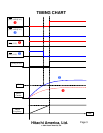
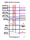
We can utilize these three functions together to create an undercurrent trip at constant
speed function. In this example, we will assume an L300P inverter. In our example, we
will use input 5 for the External Trip [EXT] signal, output relay 11 for [FA1], and output
relay 12 for [OL]. We will invert the logic of [OL] by setting C032 to “01”. This gives us
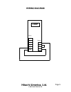
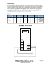
[OL]. The Table 1 below shows the necessary parameter settings. The Wiring diagram
on Page 5 shows the required signal connections. The Timing Chart on Page 3 shows
the relationship of the input and output signals. A logical “AND” between [FA1] and [OL]
is achieved by connecting the contacts in series.
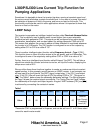
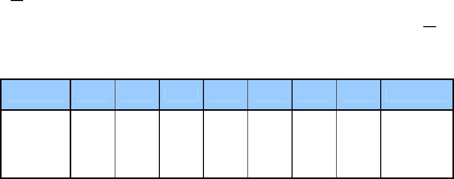
Table 1
Parameter C005 C015 C021 C022 C031 C032 C040 C041
Value
12 00 01 03 00 01 00
Desired
Low Current
Threshold
Level (A)*
*Parameter C041 is programmed in Amperes, and can be set from 0.1 to 2.0 times rated
current for each inverter model.
Hitachi America, Ltd.
© 2004 Hitachi America, Ltd.
Page 2