


vii
Table of Figures
Figure 1 The 9960 provides for exploding growth and data consolidation while the 9910
provides for managed growth and open system exploitation. ................................................2
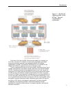
Figure 2 The Hitachi Lightning 9960 Series’ Hi-Star internal switched-fabric architecture.................3
Figure 3 System block diagram of the 7700E’s shared bus architecture...............................................4
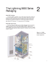
Figure 4 A 9960 Control Frame and its major components. ..............................................................7
Figure 5 A 9960 Array Frame with its major components...................................................................8
Figure 6 A power supply module of a Lightning 9900 Series system...................................................9
Figure 7 A 9910 single-cabinet storage subsystem.............................................................................10
Figure 8 Fibre Channel and ESCON or FICON adapter boards connect to open systems and
mainframe computers. ........................................................................................................11
Figure 9 A Fibre Channel host adapter board and its major hardware components...........................12
Figure 10 An ESCON host adaper board and its major hardware components...................................13
Figure 11 A 9960 system connected to Mainframes and Open Systems hosts.....................................14
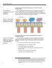
Figure 12 The Cache Hierarchical Star Network (C-HSN) provides fully redundant switched
access to cache from all channel adapters. ..........................................................................15
Figure 13 The CSW and CARBs provide non-blocking channel access to all cache...........................16
Figure 14 A shared-bus architecture is limited to two simultaneous I/O operations. ..........................17
Figure 15 The Lightning 9900 Series Hi-Star architecture allows for 16 parallel I/Os to cache
through four interconnecting cache switches.......................................................................17
Figure 16 Separate redundant control memory handles the exchange of control information between
processors and cache memory about the status, location, and configuration of data. ..........19
Figure 17 Functional diagram of a Lightning 9900 Series ACP pair. ..................................................21
Figure 18 Functional diagram of an Array Group with FC-AL disks. ................................................22
Figure 19 Diagram of four ACP pairs and 32 FC-AL back-end disks. ................................................22
Figure 20 The Lightning 9900 Series Systems are available with RAID-1+ and RAID-5 arrays. ........24
Figure 21 The Lightning 9900 offers a far more complete range of availability protection than
competitive products. ........................................................................................................26
Figure 22 Hitachi Dynamic Link Manager automatically provides path failover and load balancing
for open systems. ................................................................................................................28
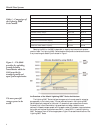
Figure 23 Test results show the advantages of the 9960 HiStar architecture when compared to a
shared bus architecture. ......................................................................................................31
Figure 24 Hitachi Data Systems offers a broad range of remote copy, data duplication, and data
migration software solutions. ..............................................................................................34
Figure 25 HiCommand allows management of virtually all Hitachi hardware and software from
the customer’s platform of choice. ......................................................................................38
Figure 26 The GUI interface on Hitachi Graph-Track simplifies performance management. ............41