


6 308-043
Service
Notes
D
Repair Kit 223–439 is available to service the
pump. For the best results, use all the kit parts.
Parts included in the kit are marked with an asterisk
in the text, for example (15*).
D
If possible, have all the necessary replacement
parts available before you begin the repair, to
reduce down time.
D
When replacing the displacement rod (36) or the
cylinder (38), always replace all of the pump pack
-
ings, seals, and glands, to ensure proper sealing.
Disconnecting the Displacement Pump
WARNING
To
reduce the risk of serious injury whenever you
are instructed to relieve pressure, always follow the
Pressure Relief Procedure
on page 5.
1.
Solvent flush the pump if possible. Then,
relieve
the pressure
.
2.
Disconnect the hoses from the pump. Remove the
pump from its mounting and clamp it in a vise.
3.
Disconnect the displacement pump from the motor
as explained in your separate pump manual.
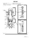
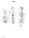
Intake
V
alve (Fig. 1)
1. Remove
the hex nuts (13) and washers (14) from
the tie rods (32). Unscrew the tie rods from the
intake valve (42). Remove the intake valve from
the pump.
2.
Disassemble the intake valve. Take note of which
set of holes the ball stop pin (28) is in.
3.
Clean all parts thoroughly
, and inspect them for
wear or damage. Replace parts as needed.
4.
Reassemble the valve. Place the ball stop pin (28)
in the same holes from which it was removed. If
you want to change the fluid flow through the
pump, place the pin in a dif
ferent set of holes.
Refer to
Check V
alve Adjustment.
5.
If no further service is needed, reinstall the intake
valve on the pump. T
orque the hex nuts (13)
evenly to 50–60 ft-lb (68–81 N
S
m), using a criss-
cross tightening pattern.
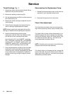
Piston (Fig. 1)
1. Remove
the intake valve as explained in
Intake
Valve.
2.
Pull the cylinder (38) down, off the piston assem
-
bly.
3.
Unscrew the piston retainer screws (25). Remove
the piston parts from the displacement rod (36).
4.
Clean all parts thoroughly
, and inspect them for
wear or damage. Replace parts as needed.
5.
Place the gasket (49) and ball (16) on the piston
retainer (43). Install these parts in the displace
-
ment rod.
NOTE:
The piston retainer (43) must not obstruct the
ports in the displacement rod (36).
6.
Install one cup packing (31*) on the displacement
rod (36). Be sure the lips of the packing face up.
7.
Install the packing spacer (30). Position one cup
packing (31*) on the displacement rod so the lips
of the packing face down.
8.
Install the piston guide (35). Install the four screws
(25) through the piston assembly and screw them
into the displacement rod (36). T
orque the screws
evenly to 30–40 ft-lb (41–54 N
S
m), using a criss-
cross tightening pattern.
9.
If no further service is needed, go to
Throat Pack
-
ings.
If no further service is needed, slide the
cylinder (38) and gaskets (24*) over the piston
assembly
. Install the intake valve. T
orque the nuts
(13) evenly to 50–60 ft-lb (68–81 N
Sm).