


2
Maintenance
Make certain that
power source is
disconnected before attempting to
service or disassemble any components!
If power disconnect is out-of-sight, lock
it in open position and tag it to prevent
application of power.
MECHANICAL SEAL REPLACEMENT
Refer to Figures 2 and 3.
IMPORTANT: Always replace both seal
seat (Ref. No. 9) and seal head (Ref. No.
10) to insure proper mating of
mechanical seal components!
NOTE: It is not necessary to remove
piping from pump casing. Motor and
impeller assembly is removed from back
of casing.
1. Drain pump before disassembling
Unscrew pipe plug (Ref. No. 14) to
drain most of liquid; some will be left
in bottom.
2. Unthread fasteners (Ref. No. 5) and
remove pump casing (Ref. No. 13)
and casing seal (Ref. No. 8) from
casing cover (Ref. No. 7).
3. To unscrew impeller (Ref. No. 12),
turn counterclockwise (CCW) facing
impeller.
NOTE: A screwdriver slot or two flats
for use with an open end 7/16" wrench,
are provided at rear of motor shaft
(remove bearing cap for access). To hold
motor shaft from turning, either insert
a large screwdriver blade into slot, or
use a 7/16" wrench across flats.
4. Unthread fasteners (Ref. No. 6) and
remove motor adapter (Ref. No. 4).
Seal head and impeller shims (Ref.
No. 11) will come loose at this time.
NOTE: Casing cover will still be attached
to motor adapter.
IMPORTANT: Retain impeller shims for
use when reassembling unit.
5. Push seal seat from casing cover
with screwdriver.
6. Clean adapter recess before
inserting a new seal seat.
7. Carefully wipe polished surface of
new seal seat with a clean cloth.
8. Wet outside of rubber portion of
seal seat with a light coating of
soapy water.
9. Press new seal seat squarely into
cavity in casing cover. If seal seat
does not press squarely into cavity, it
can be adjusted into place by
pushing on it carefully with a piece
of pipe or dowel. Always use a piece
of cardboard between pipe and seal
seat to avoid scratching seal seat.
(This is a lapped surface and must be
handled very carefully.)
10. After seal seat is in place, insure that
it is clean and has not been marred.
Specifications Information and Repair Parts Manual
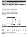
1-Inch Self-Priming Centrifugal Pumps
Low Volume Liquid Transfer Bronze
5660-97 thru 5669-97
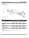
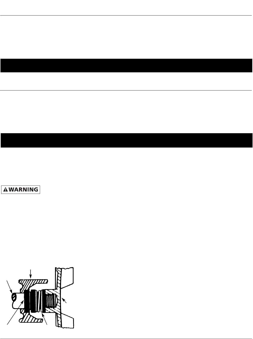
Figure 2 - Mechanical Seal Replacement
Impeller
Motor
shaft
Adapter
Seal head
Seal seat
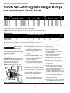
Specifications
DRIVER PUMP Ship
Power NEMA Weight
Model HP Phase Enclosure Supply Hertz Frame RPM Casing Adapt. Imp. Seals‡ (Lbs.)
5660-97 1/2 1 ODP 115/230 VAC 60 56J 3450 BR BR BR Buna N 38
5661-97 3/4 1 ODP 115/230 VAC 60 56J 3450 BR BR BR Buna N 39
5662-97 1 1 ODP 115/230 VAC 60 56J 3450 BR BR BR Buna N 42
5664-97 2 1 ODP 115/230 VAC 60 56J 3450 BR BR BR Buna N 60
5665-97 1/2 1 TEFC 115/230 VAC 60 56J 3450 BR BR BR Buna N 41
5666-97 3/4 1 TEFC 115/230 VAC 60 56J 3450 BR BR BR Buna N 43
5667-97 1 1 TEFC 115/230 VAC 60 56J 3450 BR BR BR Buna N 46
5669-97 2 1 TEFC 115/230 VAC 60 56J 3450 BR BR BR Buna N 65
(ODP) Open Drip Proof; (TEFC) Totally Enclosed Fan Cooled; (BR) Bronze
(‡) Shaft seal also contains carbon, ceramic, and stainless steel components.
NOTE: Driver data is subject to change without notice, see label on driver for actual specifications.
Performance
GPM of Water at Total Head in Feet
Max.
Model HP 10' 20' 30' 40' 50' 60' Head**
5660-97, 5665-97 1/2 38 30 20 9 — — 47 ft.
5661-97, 5666-97 3/4 56 48 37 24 7 — 53
5662-97, 5667-97 1 70 61 50 38 24 — 60
5664-97, 5669-97 2 90 83 74 64 50 28 68
(**) Shutoff; to convert to PSI, multiply by SG (specific gravity of liquid), then divide by 2.31.