


Specifications Information and Repair Parts Manual 4445-95, 4446-95, 5570-95, 5571-95 and 5572-95
Vertical Sealless Sprayer/Washer Pumps
Maintenance
WARNING Make certain that unit
is disconnected from power
source before attempting to
service or remove any component.
IMPELLER/MOTOR REPLACEMENT
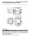
Refer to Figure 2, and 3.
1. Remove unit from the tank or
reservoir.
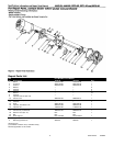
2. Remove fasteners (Ref No. 8) and
washers if present (Ref. No. 7) that
connect the volute base (Ref. No. 17)
to the volute cover (Ref. No. 10).
3. Remove volute base, and gasket
(Ref. No. 16).
4. Place an allen wrench through the
slot in the top of the column and into
one of the socket head screws of the
shaft coupling. Rotate impeller
counterclockwise until allen wrench
stops against side of slot. Remove nut
(Ref. No. 15) and then impeller from
drive shaft by rotating each
counterclockwise.
IMPORTANT: Care should be taken to
insure that same number of shim
washers (Ref. No. 9), if present, is
replaced behind impeller as were
removed. These shim washers are
located directly behind the impeller.
Shim washers may or may not be
present depending on assembly
clearances.
5. Remove allen wrench from slot and
then remove the four fasteners (Ref.
No. 5) and washers or nuts (Ref. No. 4)
that connect the motor (Ref. No. 1) to
the column (Ref. No. 3).
6. Remove the motor with shaft (Ref.
No. 13) and coupling (Ref. No. 2) from
the column.
7. Measure the distance from the
shaft coupling to the motor mounting
surface. Record this measurement.
8. Loosen the two socket head screws,
towards the motor, in the coupling.
Slide the coupling/shaft from the
motor.
9. To reassemble, slide the
coupling/shaft on the motor. Replace
drive key (Ref. No. 7) if removed (557?
Series only). Position the coupling at
the recorded distance from the motor
mounting surface. Securely tighten all
four socket head screws in coupling.
10. Install motor/shaft assembly into
column. Secure with four fasteners
and washers.
11. Install impeller, shim washers if
any, and nut. Position gasket on
volute cover and install volute base
with fasteners and washers.
IMPORTANT: If impeller strikes volute
spacer plate (Ref. No. 11) before
bottoming on shaft shoulder, add two
0.020” shims behind impeller.
Reinstall impeller.
12. Place pump in an upright position.
Rotate shaft/impeller. Impeller cannot
strike volute base or volute cover. If
interference exists, install or remove
shim washers behind the impeller.
(See “SHIM ADJUSTMENT” section) If
shimming does not correct
interference, repositioning
coupling/shaft/impeller assembly on
motor shaft may be necessary.
VOLUTE SPACER PLATE
REPLACEMENT
The volute spacer plate is subject to
wear only by abrasive liquids. If badly,
worn this plate can be replaced easily.
1. Disassemble pump for access as
described in IMPELLER/MOTOR
REPLACEMENT, steps 1, 2, 3, and 4.
2. Remove two fasteners (Ref. No. 12)
that connect the spacer plate to the
volute cover.
3. Replace spacer plate.
4. Reassemble pump as described in
steps 11 and 12.
SHIM ADJUSTMENT
1. When installing a replacement
impeller (Ref. No. 14), motor (Ref. No.
1), volute spacer plate (Ref. No. 11) or
volute base (Ref. No. 17), it may be
necessary to adjust the number of
shims (Ref. No. 9) to insure proper
running clearance between impeller
and volute base and spacer plate.
Proceed as follows:
NOTE: A proper running clearance
between impeller and volute base is
0.04” to 0.06”.
2
1. For impeller or motor replacement,
add one 0.020” shim in addition to
those removed, if any, originally.
2. Reassemble pump as described in
steps 9, 10, 11, and 12 as described in
IMPELLER/MOTOR REPLACEMENT.
IMPORTANT: Insure that volute base
is snugly in place and check shaft to
make sure it is turning freely (rotate
impeller by using impeller nut Ref.
No. 15 and socket wrench). Tighten
fasteners connecting motor to column
and volute to base carefully. Rotate
shaft while tightening so that motor
bearings are not damaged in the
event that too many shims were
installed. If shaft seizes before
fasteners are completely tight,
disassemble pump and remove two
shims and repeat assembly.
SHAFT SUPPORT REMOVAL
Models 4445-95 and 4446-95 only.
These units are designed to operate
without a bottom bearing. A shaft
support (Ref. No. 20) is installed at the
factory to protect the shaft from
misalignment during shipping. If
pump is noisy while operating, this
support may be the cause. The shaft
support can be removed to stop noisy
operation. Shaft support should not
be replaced.
1. Disassemble pump for access as
described in IMPELLER/MOTOR
REPLACEMENT, steps 1 through 6.
2. Press out shaft support. Do not
remove support plate (Ref. No. 21).
3. Reassemble pump as described in
steps 10, 11, and 12.
DEBRIS SCREEN CLEANING
Sprayer/Washer pumps are equipped
with a debris screen (Ref. No. 18). This
screen is supplied attached to volute
base (Ref. No. 17) with 4 drive pins.
This screen may be replaced if
damaged.
If pump performance is reduced or
severe vibration occurs during
operation this screen may be clogged.
Debris screen must be thoroughly
cleaned to restore pump
performance.