


6
START CAPACITOR REPLACEMENT
1. On single phase motors only, to gain access to the motor
start capacitor (376), follow steps 1 through 5 in the
“POWER CABLE REPLACEMENT” section of this
manual.
NOTICE: DISCARD STRAIN RELIEF ASSEMBLY.
IT CAN NOT BE REUSED.
FAILURE TO DRAIN CAPACITOR
OF STORED ELECTRICAL
CHARGE BEFORE SERVICE CAN
CAUSE A SEVERE SHOCK.
2. Remove the capacitor retaining screw and retaining
bracket from the motor assembly. Remove the two wires
from the capacitor. Discard the capacitor.
3. Connect the two motor wires to the new capacitor and
reassemble with the retaining bracket and retaining
screw, tightening securely.
4. Reassemble unit following steps 6 through 12 in the
“POWER CABLE REPLACEMENT” section of
this manual.
NOTICE: FOLLOW THE INSTRUCTIONS PROVIDED
IN THE “WIRING AND GROUNDING” AND
“OPERATION” SECTIONS OF THE
MANUAL AFTER UNIT DISASSEMBLY,
REASSEMBLY.
MOTOR REPLACEMENT
1. To gain access to the motor assembly, follow steps 1
through 5 in the “POWE R CABLE REPLACEMENT ”
section of this manual.
NOTICE: DISCARD STRAIN RELIEF ASSEMBLY.
IT CAN NOT BE REUSED.
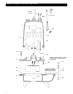
2. Remove the four motor thru bolts and carefully pull
motor assembly from bearing housing. Further motor
service MUST be provided by a qualified motor repair
facility.
3. Insert the motor assembly into the bearing housing,
visually aligning the motor thru bolts through the lower
motor vent openings.
4. Install the four motor thru bolts, torquing to 35 lbs in
(4 Ν m).
5. To complete the assembly follow steps 6 through 12 in
the “POWER CABLE REPLACEMENT” section of
this manual.
NOTICE: FOLLOW THE INSTRUCTIONS PROVIDED
IN THE “WIRING AND GROUNDING” AND
“OPERATION” SECTIONS OF THE
MANUAL AFTER UNIT DISASSEMBLY,
REASSEMBLY
WARNING
Hazardous
voltage
7. Connect the power cable leads to the motor assembly as
follows:
• Single Phase Motors – Connect the BLACK wire to
motor terminal L
1
. Connect the WHITE wire to
motor terminal L
2
. Connect the GREEN wire to the
motor ground.
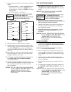
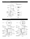
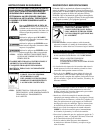
• Three Phase Motors – See Figure 1.
FAILURE TO CONNECT POWER
AND SENSOR WIRES TO
DESIGNATED WIRES CAN CAUSE
SHOCK, BURNS OR DEATH.
Figure 1
8. Wire tie the power cable to the motor assembly.
9. Slide the motor cover onto the motor assembly, while
carefully pulling the power cable out through the motor
cover hole. DO NOT damage cables. Install the four
seal housing socket head screws, torquing to 90 lbs in
(10 Ν m).
10. Install the power cable strain relief assembly torquing
the nylon bushing to 75 lbs in (8.5 Ν m) and the steel
bushing to 100 lbs in (11.3 Ν m).
11. Continue the assembly following steps 7 through 12 of
the “MECHANICAL SEAL REPLACEMENT”
section of this manual.
12. If the motor cover was replaced, it is necessary to
transfer the Goulds nameplate. Using two stainless steel
No. 2 round head metallic drive screws, install the
Goulds nameplate.
NOTICE: FOLLOW THE INSTRUCTIONS PROVIDED
IN THE “WIRING AND GROUNDING” AND
“OPERATION” SECTIONS OF THE
MANUAL AFTER UNIT DISASSEMBLY,
REASSEMBLY.
WARNING
Hazardous
voltage
1
7
2
8
3
9
6
5
4
MOTOR LEADS
L
1
L
2
L
3
G
208-230 V 3/60
7
4
MOTOR LEADS
L
1
L
2
L
3
G
460 V 3/60
8
5
9
6
1
2
3
POWER CABLE LEADS
POWER CABLE LEADS
THREE PHASE MOTOR WIRING DIAGRAM