


Operating Instructions and Parts Manual
Models 020598 and 020599
5
Operation (continued)
one or two minutes. A suction lift of
20 feet can take 5 minutes running
time to pick up a prime. If pumping
does not start within this time, shut
off the engine, let unit cool down
about 5 minutes, refill pump casing
and retry. If engine does not start,
refer to Engine Manual. If pump
does not prime after 2 tries, refer to
“Troubleshooting Chart” in this man-
ual.
6. Properly fueled and lubricated, the
pump/engine unit will run automati-
cally without attention to the con-
trols. The gasoline engine has a built-
in governor and will adjust the speed
of the engine automatically depend-
ing on the volume of water being
delivered.
Even though this
unit will operate
with minimal supervision, it should not
be left operating by itself. Depending
on the application and area unit is oper-
ating (high traffic, people in area, etc.)
will dictate the necessity of having
someone watching over the unit.
Maintenance
To prevent acciden-
tal starting always
remove spark plug, or disconnect and
ground spark plug wire before attempt-
ing to service or remove any compo-
nent.
1. If the pump is located in an area sub-
ject to freezing temperature, the
pump should be drained when not in
operation. Also, the pump should be
flushed after each use.
2. Clean the suction line strainer at reg-
ular intervals.
3. If the gas engine is equipped with a
spark arrestor screen in the muffler,
it should be inspected for wear peri-
odically, and replaced when neces-
sary.
NOTE: For information pertaining to
the engine and engine parts, consult
the Engine Manual or contact the near-
est authorized service representative or
the manufacturer.
4. Periodically check nuts and bolts on
engine, mounting frame and pump.
Since this is a gas engine pump,
vibration levels tend to loosen nuts
and bolts faster than normal. Use
Loctite (thread sealant) on threads or
lockwashers if necessary.
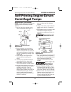
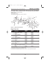
MECHANICAL SEAL REPLACEMENT
Refer to Figures 1, 2, and 3.
IMPORTANT: Replace seal seat, (Ref.
No. 22) and seal head (Ref. No. 23) at
the same time to ensure proper mating
of mechanical seal components!
1. Unthread fasteners (Ref. No. 16), nuts
(Ref. No. 25) and remove casing (Ref.
No. 15) and casing seal (Ref. No. 7)
from adapter (Ref. No. 3). Unthread
fasteners (Ref. Nos. 11 and 19) and
remove volute (Ref. No. 20) and
volute seal (Ref. No. 6) from adapter.
2. Unthread impeller fastener (Ref. No.
10) and remove impeller (Ref. No. 9),
impeller seal (Ref. No. 4) and shims
(Ref. No. 21).
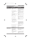
Performance Chart
GPH of Water at Total Head in Feet Max.
Model 10' 20' 30' 40' 50' 60' 70' 80' 90' Head*
020598 8460 7680 6840 6000 5100 4140 3180 2100 840 94 ft.
020599 8460 7920 7440 6960 6360 5760 5040 4200 3360 125
(*) Shut-off; to convert to psi, divide by 2.31
Document2 9/3/03 5:48 PM Page 5