22
USER GUIDE
USING THE BOILER
Your system should be serviced at least once a year
by a qualified engineer.
If the boiler is subject to heavy use, it may require
servicing more than once a year - consult your service
engineer for advice.
Starting the burner:
In normal operation, the burner starts automatically
whenever the boiler temperature falls below the set
temperature.
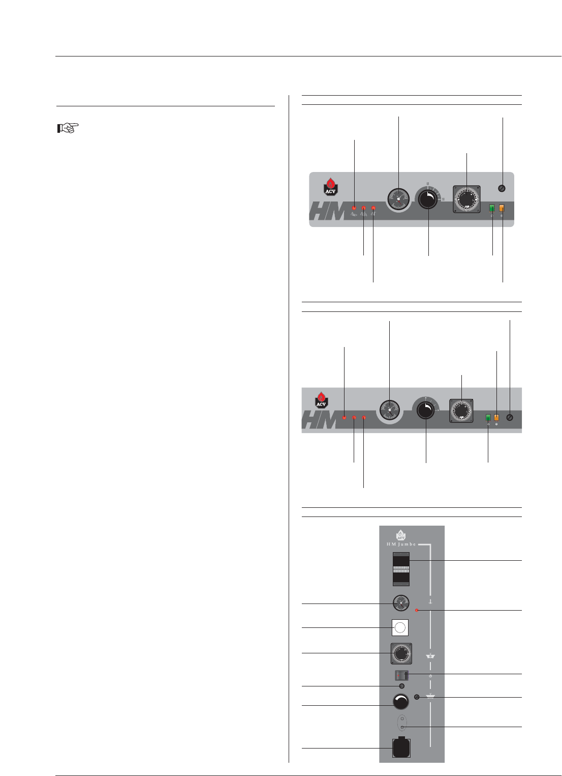
Understanding the control panel
There are no user parts inside the control panel.
1. On/Off switch
This turns the HeatMaster on or off.
2. Control thermostat - 60 to 90 °C
When using the HeatMaster as a hot water generator only, the
temperature can be set between 60 °C and 90 °C.
If the HeatMaster is used for both hot water and central heating, the
control thermostat would normally be set at 80 °C to achieve optimum
operating conditions.
3. Summer/Winter switch
This turns the heating pump (if fitted) on or off.
4. Manual reset high limit thermostat
If the boiler temperature exceeds 103 °C this safety device will
activate and the high temperature indicator will light up. To reset -
first allow the boiler to cool to below 60 °C, unscrew the cap and
press the reset button using a pencil or similar pointed device,
replace the cap. If the fault persists, turn the boiler off and call an
engineer.
5.Time clock
This allows the HeatMaster to be timed on and off and operates on
a 24 hour sequence. Around the outside of the clock there are a
number of white tabs, these allow 15 minute switching periods. To
set the time clock simply push outwards the number of tabs required
for ON period.
Remember: TAB IN = HeatMaster OFF
TAB OUT = HeatMaster ON
6.Temperature and pressure gauge
This gauge indicates both the temperature of the HeatMaster and
the pressure within the primary circuit.
The temperature should not exceed 90 °C - if it does, switch the
boiler off and check the thermostat setting. If the fault persists, call
an engineer.
The pressure should not fall below 1bar, if it does the please see the
'Heating System Pressure' paragraph later in this section.
7. Low primary water pressure indicator
If this indicator lights up, the primary circuit of the HeatMaster requires
topping up with water. Please see the 'Heating System Pressure'
paragraph later in this section.
Control panel HeatMaster 60 N
I
O
Manual reset high
limit thermostat
Burner
lockout
indicator
Combined temperature
and pressure gauge
Time clock
Control
thermostat
ON / OFF
switch
Primary circuit low
water pressure
indicator
High limit cutoff
indicator
Summer / Winter switch
bar
1
8
1
7
1
6
1
5
1
4
1
3
1
2
1
1
1
0
9
8
7
6
5
4
3
2
1
2
4
2
3
2
2
2
1
2
0
1
9
GRASSLINGRASSLIN
I
O
.
.
.
.
.
.
.
.
.
.
.
.
.
.
.
.
.
.
Servicing socket
(230 V ˜ 50 Hz)
Fuse
Control thermostat
Relay base
Time clock
Combined temperature
and pressure gauge
Thermal reset high
limit thermostat
ON / OFF switch
Manual reset high
limit thermostat
Primary circuit low
water pressure indicator
Mains power
electrical connection
(multi-pin plug)
Control panel HeatMaster 150 Jumbo
I
O
Manual reset high
limit thermostat
Burner
lockout
indicator
Combined temperature
and pressure gauge
Time clock
Control
thermostat
ON / OFF
switch
Primary circuit low
water pressure
indicator
Summer / Winter switch
High limit cutoff
indicator
Control panel HeatMaster 70 N and HeatMaster 100 N


