


2
595-5295-11
INSTALLATION
For easy installation, select an existing light with a wall
switch for replacement.
For best performance, mount the fixture about 8 ft.
(2.4 m) above the ground.
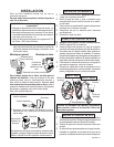
WIRE THE LIGHT CONTROL.
❒ Turn the power to the lighting circuit off at the
fuse or circuit breaker box.
❒ Remove the existing light fixture.
❒ Install mounting strap to junction box using screws
appropriate for your junction box.
❒ The plastic hanger can be used to hold the fixture
while wiring. The small end of the plastic hanger
can be threaded through the hole in the center of
the cover plate. The small end then goes into one
of the slots on the mounting strap.
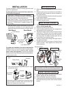
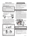
❒ Thread all fixture wires through the large holes in
the gasket as shown.
❒ Connect the junction box wires to the light fixture
wires as shown. Twist together and secure with
wire connectors.
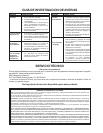
BULB INSTALLATION.
❒ When relamping, turn power off and let the fixture
cool.
❒ Remove glass cover and remove the old bulb by
pushing the bulb towards the socket indicated on
the metal reflector.
❒ To insert the new bulb, follow the instructions printed
on the metal reflector.
❒ Check that the bulb is seated properly.
❒ Reinstall the glass cover.
CAUTION: To Avoid Fire Or Burn Hazards:
• Allow fixture to cool before touching. The bulb and
the fixture operate at high temperatures.
• Keep fixture at least 1" (2.5 cm) from combustible
materials. Do not aim at objects closer than 3 ft. (1 m).
• Use only T3, 250W (max.) tungsten halogen 120
VAC lamps.
White to White
Black to Black
Connect any fixture ground wire(s) and the cover
plate ground screw to the junction box ground wire.
Gasket
Mounting Strap
Mounting
Bolt
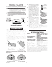
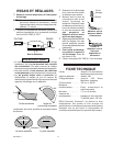
MOUNT THE LIGHT CONTROL.
❒ Align the Light Control cover plate and cover plate
gasket. Secure with the mounting bolt.
❒ Push the Rubber Plug firmly into place.
❒ If a wet location junction box was not used, caulk the
wall plate mounting surface with silicone weather
sealant.
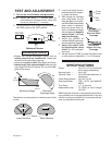
For eave mount only:
❒ Swing the sensor head towards the clamp screw
joint.
If the sensor pops out of the ball joint, loosen the clamp
screw and push the sensor back into the ball joint.
Tighten the clamp screw when done.
❒ Then rotate the sensor head clockwise 180° so the
controls face down.
Controls
Eave Mount
For under eave installation, the sensor head must be
rotated as shown in the next two steps for proper opera-
tion and to avoid the risk of electrical shock. Also for
proper under eave operation, remove the protective
backing from the Light Shield and stick on as shown below.
Controls
Controls
Clamp Screw
Wall Mount
Lens Retainer
Light Shield,
with opening at
this side
❒ Note the position of the various parts of the fixture
for the type of installation for your application and
adjust the lamp head and sensor as shown below.
Lens Retainer
Light Shield
Opening
Rubber
Plug