


2
598-1153-02
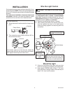
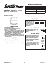
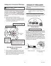
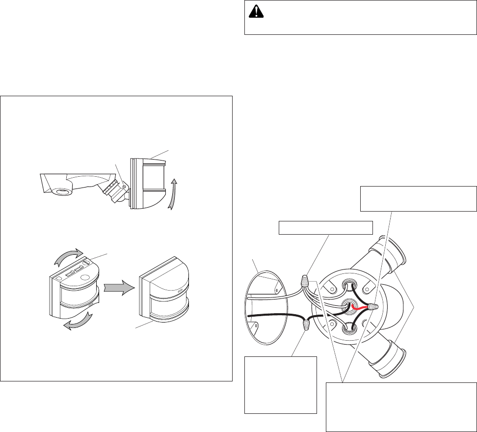
Wire the Light Control
Junction Box
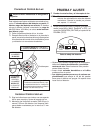
Mount the Light
❒ Follow the instructions that came with your light
fixture for mounting and adjusting the light fixture.
❒ Keep regular PAR-38 bulbs at least 1" (25 mm)
from the sensor. Halogen bulbs should be kept at
least 2" (51 mm) from the sensor.
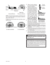
For eave mount only:
❒ Swing the sensor head towards the clamp screw
joint.
If the sensor pops out of the ball joint, loosen the
clamp screw and push the sensor back into the ball
joint. Tighten the clamp screw when done.
❒ Then rotate the sensor head clockwise 180° so
the controls face down.
Controls
Clamp Screw
Controls
Controls
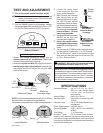
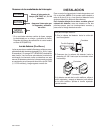
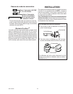
INSTALLATION
For best performance, mount the fixture about 8 ft. (2.4 m)
above the ground.
NOTE:
If fixture is mounted higher than
8 ft. (2.4 m), aiming the sensor down will reduce coverage
distance.
For under eave installation, the sensor head must
be rotated as shown in the next two steps for proper
operation and to avoid the risk of electrical shock.
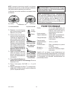
WARNING: Turn power off at circuit breaker
or fuse.
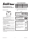
Bulb Holders
Optional: Connect additional load
across the white and red wires. Total
lighting load including bulb holders on
fixture must not exceed 500W (4.2A).
3. BLACK
CONTROL
WIRE &
BLACK
JUNCTION BOX
WIRE
1. ALL WHITE WIRES
2. RED CONTROL WIRE &
BLACK FIXTURE WIRES
These instructions show the sensor wired to floodlamps.
The white sensor wire is neutral. The black sensor
wire is hot. The red wire is the switched “hot” wire. The
lighting load (500 Watts, 4.2 A max. incandescent only)
is placed across the white and red wires.
❒ Remove the existing light fixture, if present.
❒ After screwing the sensor into the wall plate, con-
nect the junction box wires to the light control
wires by twisting together and securing with wire
connectors.