


-2-
598-1313-00
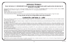
CHIME REPLACEMENT INSTALLATION
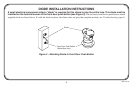
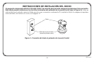
IMPORTANT: Proper installation requires a diode on the front
door push button. See Diode Installation Instructions (page 5)
after completing steps 1 through 13 below.
Note: Electrical work must be in accordance with national and local
electrical codes. If in doubt, consult a qualified electrician.
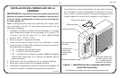
1. Verify transformer power rating. Power must be supplied from
a 16 Volt AC, 10 Watt or a 16 Volt AC, 15 Watt transformer
(Heath
®
/Zenith models 122C, 121AC, or 125C).
2. Remove cover from existing chime.
3. Label all wires before disconnecting. Using masking tape, mark
each wire according to existing chime terminal markings.
• “F” – Front Push Button Wire
• “T” – Transformer Wire
• “R” – Rear Push Button Wire (Note: Some installations may
not include rear door push button.)
4. Disconnect all wires from existing chime.
5. Remove existing chime base from wall.
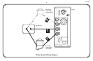
6. Determine proper chime base orientation. The chime cover
style will determine orientation.
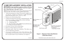
7. A cover pin is installed on two sides of the chime base. After
determining correct orientation, remove, turn over, and reinstall
the cover pin located on top of chime base (see Figure 1).
Illustrations may vary from actual chime unit.
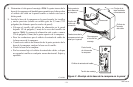
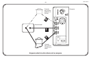
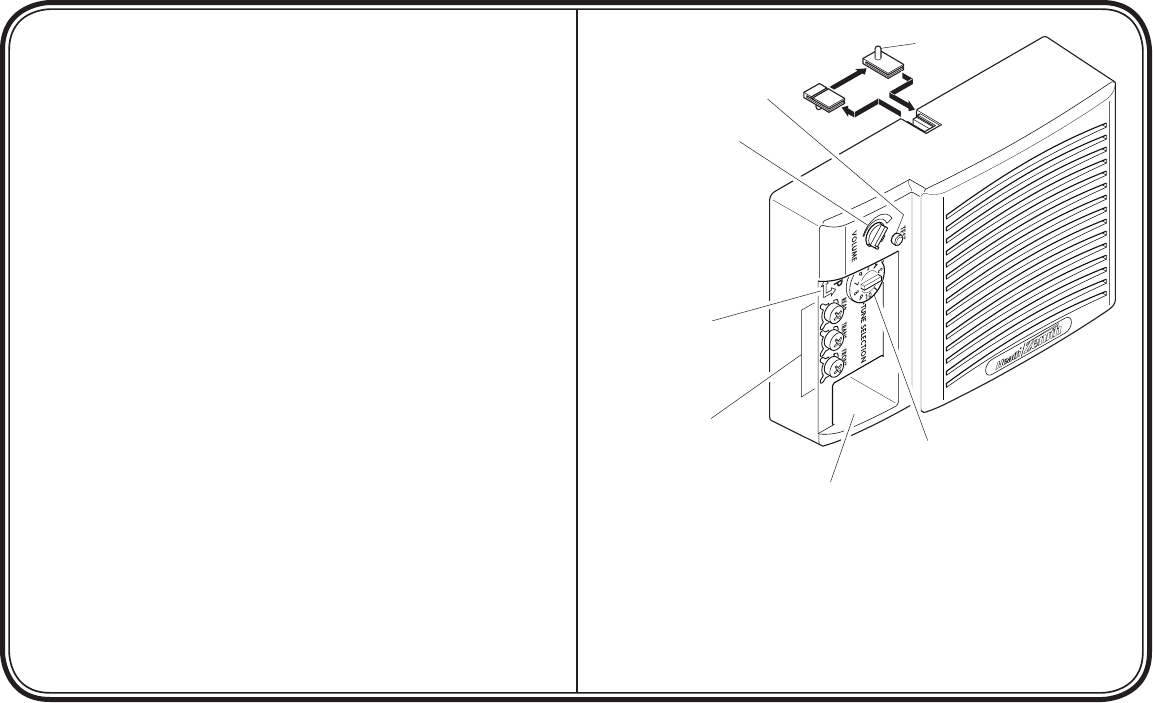
Figure 1 - Electronic Chime Identification
(2300 Base Shown)
Cover Pin
Volume Control
Base Orientation
Marking
Wire Entrance Hole
Front Door Tune Selection
Switch (3 Selections or
10 Selections
– Depending on Model)
Transformer and
Push Button Wire
Connections
Continued
Test Button