


7
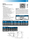
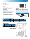
Features
• Molded Lexan® fan guards
• Coils have copper tubes with aluminum ns, mechanically-
bonded for ecient heat transfer. The coils are dehydrated
and sealed
• Textured aluminum cabinet
• Knockouts are conveniently located for refrigerant lines
• Screws are hardened, stainless steel with a bright
zinc plating
• Expansion valve mounts inside the cabinet and
connections are sweat-type
• Motors are thermally protected and
permanently lubricated
• Master units include the basic unit plus factory mounted
expansion valve, solenoid, and temperature control. Also
right-hand piping extended 8” - 12” outside the housing,
sealed and pressurized to 20 - 30 PSI. A 1/4” OD liquid feed
to slave is included
• Slave units include the basic unit plus factory mounted
expansion valve with left-hand piping extended 8” - 12”
outside the housing, sealed and pressurized to 20 - 30 PSI
Sweat inlet connection to reduce leaks
(are connection available as a ship loose option)
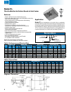
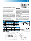
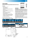
Application
Models BB are compact, wall-mounted units whose low
height makes them ideal for undercounter reach-in or drawer-
type xtures. The unit draws air in at the bottom and discharges
out the front. An optional air deector is included and can be
mounted over the center of the fan to direct air up and out. The
deector can be eld-formed to direct the air where needed,
usually onto drop-in trays of condiments in salad bar or sandwich
preparation xtures. An S-type mounting angle is included
to position the unit 3/4” o the wall which gives optimum air
circulation and performance.
The BBM (medium temperature) model is designed for 35°
to 40°F xture temperature with o-cycle defrost. The unit
is designed to operate at 10° to 17° TD and 16 hours per day
compressor run time.
The BBL (low temperature) model is designed for 0° to -10°F
xture temperature, and has automatic electric defrost. The
unit is designed to operate at 8° to 15° TD with 18 hours per
day compressor runtime. The BBL has an incoloy sheath heater
embedded in the bottom n surface for ecient and fast
defrosting. A drain pan heater is included to insure complete
condensate drainage. A disc-type sealed defrost termination/
fan delay control is mounted and wired. Field connectors are
located at the terminal board.
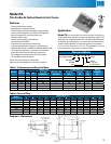
Models BBM/BBL
Back Bar Reach-In Unit Cooler
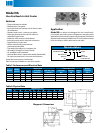
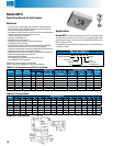
Diagram 5. Dimensions
Table 10. Physical Data
Model
Dimensions (in.) Approx.
Ship Wt. (lbs.)
A B C D E F W
BBL10 19-1/8 18 17-1/2 7-1/16 - 16-5/8 19-3/4 17
BBM11 19-1/8 18 17-1/2 7-1/16 - 16-5/8 19-3/4 16
BBL15 25-5/8 24-1/2 24 4-13/16 8-5/8 23-1/8 26-1/4 20
BBM16 25-5/8 24-1/2 24 4-13/16 8-5/8 23-1/8 26-1/4 19
Typical Section of
Sandwich Station
Model BBM
NOTES: All units have 3/8” OD suction, 1/2” OD sweat inlet and 1/2” OD drain
Table 9. Performance and Electrical Data
Model
BTUH
10°F
TD
Motor Data Defrost Heaters
CFM Qty. HP
115/1/60
Total FLA
208-
230/1/60
Total FLA
Watts
115/1/60
Amps
208-
230/1/60
Amps
BBL10 1,000 90 1 1/150 0.8 0.4 275 2.7 1.4
BBM11 1,100 90 1 1/150 0.8 0.4 - - -
BBL15 1,500 180 2 1/150 1.6 0.8 350 3.5 1.7
BBM16 1,600 180 2 1/150 1.6 0.8 - - -
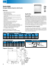
Nomenclature
BB L S 10 A G
Voltage
A = 115/1/60
B = 208-230/1/60
Back Bar Unit Cooler
Size
L = Low Temp. Unit
M = Med. Temp. Unit
Vintage
Blank = Standard Unit
S = Slave Unit
M = Master Unit