


11
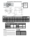
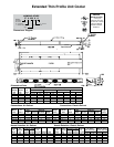
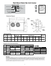
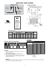
Standard or Connections (In.) Approx.
Reverse Flow Dimensions (In.) Coil Shipping
Models H L M W Inlet Suction Drain Wt. (Lbs.)
1 17
/
4
16
7
/
8
12
1
/
4
15
5
/
8
/
8
OD
/
8
OD
5
/
8
OD 19
17 19
/
4
16
7
/
8
14
1
/
4
15
5
/
8
/
8
OD
/
8
OD
5
/
8
OD 20
2 19
/
4
2
1
/
4
14
1
/
4
22
/
8
OD
1
/
2
OD
5
/
8
OD 28
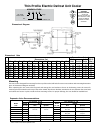
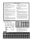
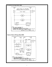
Mounting
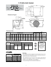
The standard ow mullion unit draws air in at the top and
discharges out the bottom. The reverse ow mullion draws air
in at the bottom and discharges out the top. The unit may be
mounted in a mullion or against a back or side wall.
When mounting to the mullion of under counter refrigerators,
mounting holes are located on both ends of the unit for attaching
to “customer furnished” mounting brackets.
When wall mounted, four “L” type brackets and eight stainless
steel sheet metal screws are provided to attach the brackets to
side panels.
IMPORTANT: A minimum of 2 inches must be provided
between the top of the unit and the top of the cabinet.
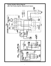
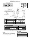
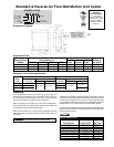
Standard & Reverse Air Flow Wall Mullion Unit Cooler
Dimensional Data
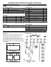
25°F Sat. Suction Temp. 20°F Sat. Suction Temp.
Model BTUH @ R-22 BTUH @ R-22
Size 10°F TD Alco Sporlan 15°F TD Alco Sporlan
1 100 1950
17 1700 HFS-1/4HC EFV-1/5C 2550 HFS-1/4HC
2 200 450
Expansion Valve Recommendations
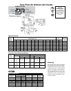
Part Standard Reverse
Description Down Flow Up Flow
115V Motor 2500701 2500701
208/20V Motor 2500801 2500801
Fan Blade 5102C 5117C
Fan Guard (1-17) 5076E 5076E
Fan Guard (2) 5077E 5077E
Motor Mount 91179001 91179001
Drain Pan (1-17) 74422002 74422002
Drain Pan (2) 7446002 7446002
FOR FOOD
SERVICE
INSTALLATIONS
. . . seal any joint
between unit cooler and
cooler liner with a sealant
listed by the National
Sanitation Foundation,
Standard 51
A top barrier is supplied and must be used if combustible material
is above the unit. On reverse ow models the barrier may be used
to direct the air straight out or up at a 45° angle. Holes and slots
are provided to adjust the barrier. If noncombustible material is
used above the unit, the barrier may be discarded if desired.
Knockouts are provided for bringing the refrigerant piping through
either end of the cabinet. An electrical knockout is provided into
an internal junction box.
Dimensional Diagram
NOMENCLATURE
XXX K 13 A G
KM = Standard Vintage
Air Flow
RAM=
Reverse
Air Flow A = 115-1-60
K =
Coated Coil
B = 208/20-1-60
Size
EFV-1/C
EFV-1/5C
Replacement Parts
Commercial Refrigeration Parts