


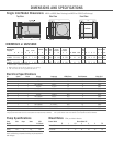
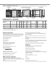
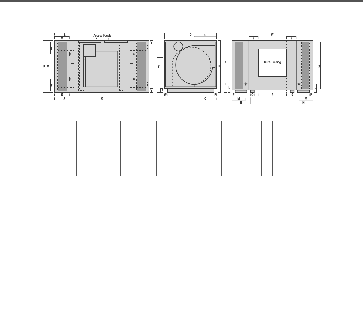
Dual Inlet Model Dimensions MD628 or UD980 (Down Discharge), MS628 or US980 (Side Discharge) and MU628 (Up Discharge)
(DOWN)
(UP)
Top View Side View - Blower Section Front View
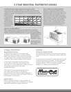
Media Section Cabinet Duct Location Drain
1
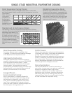
Media Blower Water
2
Electric
3
Blower Wheel Blower Skid Location Media Pad
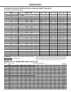
Model Number Location Cabi- Cabi- Service Service Pulley Dimension Area
1 Required Side Down net net Location Location Pitch
H W D A B C E F G J K L M S T Dia. Width Shaft Dia. N P Y Q R X V Sq.Ft.
DM080
or UM080 51
½ 83
1
/8 49
1
/8 31¾ 17¾ 15¼ 8¾ 13 13
3
/8 17 49
1
/8 71⁄4 12
3
/8 18 35½ 28 28 1
3
/16 18 19 1
5
/8 2 4 2½ 44
5
/8 48 14.8
DM120
or UM120 51
½ 91
1
/8 49
1
/8 31¾ 17¾ 15¼ 8¾ 13 17
3
/8 21 49
1
/8 71⁄4 16
3
/8 22 35½ 28 28 1
3
/16 18 23 1
5
/8 4 4 2½ 44
5
/8 48 14.8
1. Drain is 3/4” male hose thread.
2. Water service can be left or right for 1/4” tubing.
3. 7/8” knockout for running electrical service.
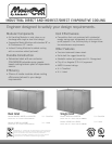
MD/MS/MU628 or UD/US980
Sizing Instructions
Follow these steps to properly size the Industrial MasterCool. The performance or
Sensible Heat Capacity of any cooler is a function of both the CFM and saturation
effi ciency (which determines the delivered air discharge temperature). Sizing by
only considering CFM may result in an improperly sized application.
1. Determine design conditions:
Outdoor Dry-Bulb DB1
Outdoor Wet-Bulb WB1
Indoor Dry-Bulb T1
2. Determine design sensible heat load (Btuh)
3. Determine leaving air temperature (LAT):
LAT = DB1 - [(DB1 - WB ) * EFF]
where EFF ‘ 0.80 for 8” media or 0.90 for 12” media
4. Determine CFM required:
CFM = 0.925 * Sensible Heat Load
(T1 - LAT)
5. Determine the cooler(s) required:
Refer to the specifi cation / air fl ow charts on next page.
6. Use KoolKalk to account for various losses:
This will result in more accurate sizing.
Motor Sheave Selection
1. Determine the external static pressure of the air delivery system.
2. Determine the motor (H.P., Voltage and Phase) required to deliver the design
airfl ow.
3. Determine the shaft size for the motor selected.
Refer to the Electrical Specifi cations chart on facing page.
4. Determine the RPM that will deliver the required airfl ow (CFM) at the static
pressure of the system.
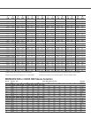
Refer to the Certifi ed Air Delivery CFM chart for the chosen cooler and selected
motor HP.
5. Determine the sheave, and the number of turns open, that is closest to the
desired RPM.
Refer to the Sheave Selection charts on the next page. Find the selected motor HP,
shaft size, and desired RPM (See Steps 2-4 above). You might need to look at more
than one sheave before fi nding the correct RPM.
6. Specify the sheave and sheave setting (turns open) for the installer.
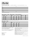
Ordering
When ordering your cooler, you should know this information.
• System design static pressure.
• Desired air volume at system design.
• Electrical power supply available.
• Stability of structure to support operating weight of unit.
Complete systems consist of the following components, and are sold separately
for application versatility.
• Cabinet – 1 blower section
• Wet media section (1 for 524’s - 2 for 628’s)
• Motor
• Motor sheave
• Pulley-belt kit
• Pump (one required for each media section)
NOTE: Motor starters, internal wiring and over-current protection are not supplied.