


Heat & Glo • VRT-AUB • 2123-980 Rev. H • 5/12
54
The gas is introduced to the appliance on the left hand side.
After the gas pipe installation is complete, check carefully
all gas connections for leaks with a commercially-available,
noncorrosive leak check solution. Be sure to rinse off all
leak check solution following testing. DO NOT USE AN
OPEN FLAME.
NOTICE: the gas supply line should be purged of any
trapped air prior to the rst ring of the unit.
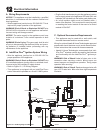
• Refer to Figure 11.1 for location of gas line access in
appliance.
• Gas line may be run through knockout(s) provided.
• The gap between supply piping and gas access hole may
be caulked with caulk with a minimum of 149 ºC continuous
exposure rating or stuffed with non-combustible, unfaced
insulation to prevent cold air inltration.
• Ensure that gas line does not come in contact with outer
wrap of the appliance. Follow local codes. Reference BS
EN 613:2001 Standard.
• Pipe incoming gas line into valve compartment.
• Connect incoming gas line to the connection on manual
shutoff valve.
WARNING! Risk of Fire or Explosion! Support control
when attaching pipe to prevent bending gas line.
• A small amount of air will be in the gas supply lines.
WARNING! Risk of Fire or Explosion! Gas build-up dur-
ing line purge could ignite.
• Purge should be performed by qualified service
technician.
• Ensure adequate ventilation.
• Ensure there are no ignition sources such as sparks
or open ames.
Light the appliance. It will take a short time for air to purge
from lines. When purging is complete the appliance will
light and operate normally.
WARNING! Risk of Fire, Explosion or Asphyxiation!
Check all ttings and connections with a non-corrosive
commercially available leak-check solution. DO NOT use
open ame. Fittings and connections could have loos-
ened during shipping and handling.
WARNING! Risk of Fire! DO NOT change valve settings.
This valve has been preset at the factory.
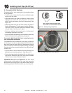
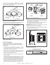
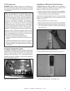
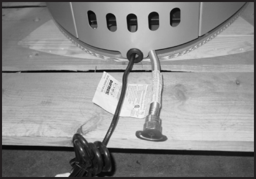
Figure 11.1
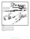
Gas line and power cord are shipped inside back panel.
To access the gas line and power cord, remove the top
plate from the appliance. Remove and retain the two
Allen head screws that hold the back panel in place.
Using the black grommet located in the component bag,
slide it into the bottom of the back panel and feed the power
cord through the grommet, as shown in Figure 11.1.