


Heat & Glo • VRT-AUB • 2123-980 Rev. H • 5/12
34
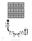
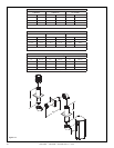
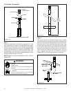
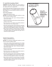
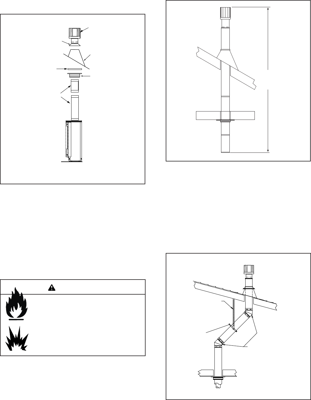
STORM COLLAR
VERTICAL
TERMINATION CAP
PIPE LENGTH
FIRESTOP
FLASHING
SUPPORT
BOX
11.58 m
(38 ft.)
MAXIMUM
On vertical terminations use SLP-TVHW.
Figure 7.20
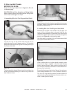
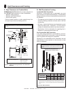
Step 1.
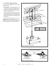
Check the installation instructions for required 10 in. (254
mm) clearances (air space) to combustibles when pass-
ing through ceilings, walls, roofs, enclosures, attic rafters,
or other nearby combustible surfaces. (See Figure 7.19).
Check the instructions for maximum vertical rise of the
flueing system, and any maximum horizontal offset limita-
tions. All offsets must fall within the set parameters of the
flueing diagrams located in Section 7.
NOTE: Maximum vertical rise allowable is 38 ft. (11.58 m)
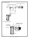
Figure 7.20.
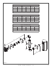
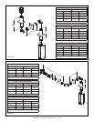
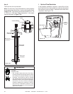
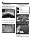
CONNECTED TO
WALL STRAP
WALL
STRAP
TWO 45 DEGREE
ELBOWS
METAL STRAP
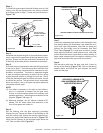
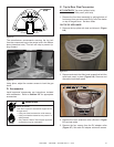
Step 2.
Set the gas stove in its desired location. Drop a plumb
bob down from the ceiling to the position of the gas stove
flue exit, and mark the location where the flue will pen-
etrate the ceiling. Drill a small hole at this point. Next, drop
a plumb bob from the roof to the hole previously drilled
in the ceiling, and mark the spot where the flue will pen-
etrate the roof. Determine if ceiling joists, roof rafters, or
other framing will obstruct the flueing system. You may
wish to relocate the gas stove, or to offset, as shown in
Figure 7.21 to avoid cutting load bearing members.
Figure 7.21
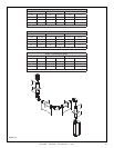
Figure 7.19
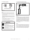
H. Vertical Termination
Fire Risk.
Explosion Risk.
Maintain ue clearance to combustibles as
specied.
• Do not pack air space with insulation or other
materials.
Failure to keep insulation or other materials
away from ue pipe may cause re.
WARNING