


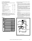
20
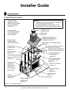
47-1/8 in.
(1197 mm)
Header Height
12 in. max.
(305 mm)
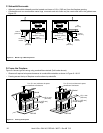
2 in. (51 mm) minimum air space
clearance to enclosure
BAY-40
2 in. (51 mm) minimum air space
clearance to enclosure
12 in. max.
(305 mm)
PIER-40
47-1/8 in. (1197 mm)
Header Height
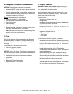
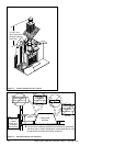
Mantel
Mantel
11.92 in.
[303 mm]
FLUSH
FRONT
40 in.
[1016 mm]
36 in.
[914 mm]
(fireplace opening)
12 in.
[305 mm]
50° angle
9 3/4 in.
[248 mm]
4 in.
[102 mm]
BRICK
FRONT
40 in.
[1016 mm]
36 in.
[914 mm]
(fireplace opening
12 in.
[305 mm]
39° angle
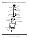
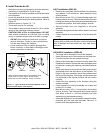
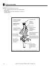
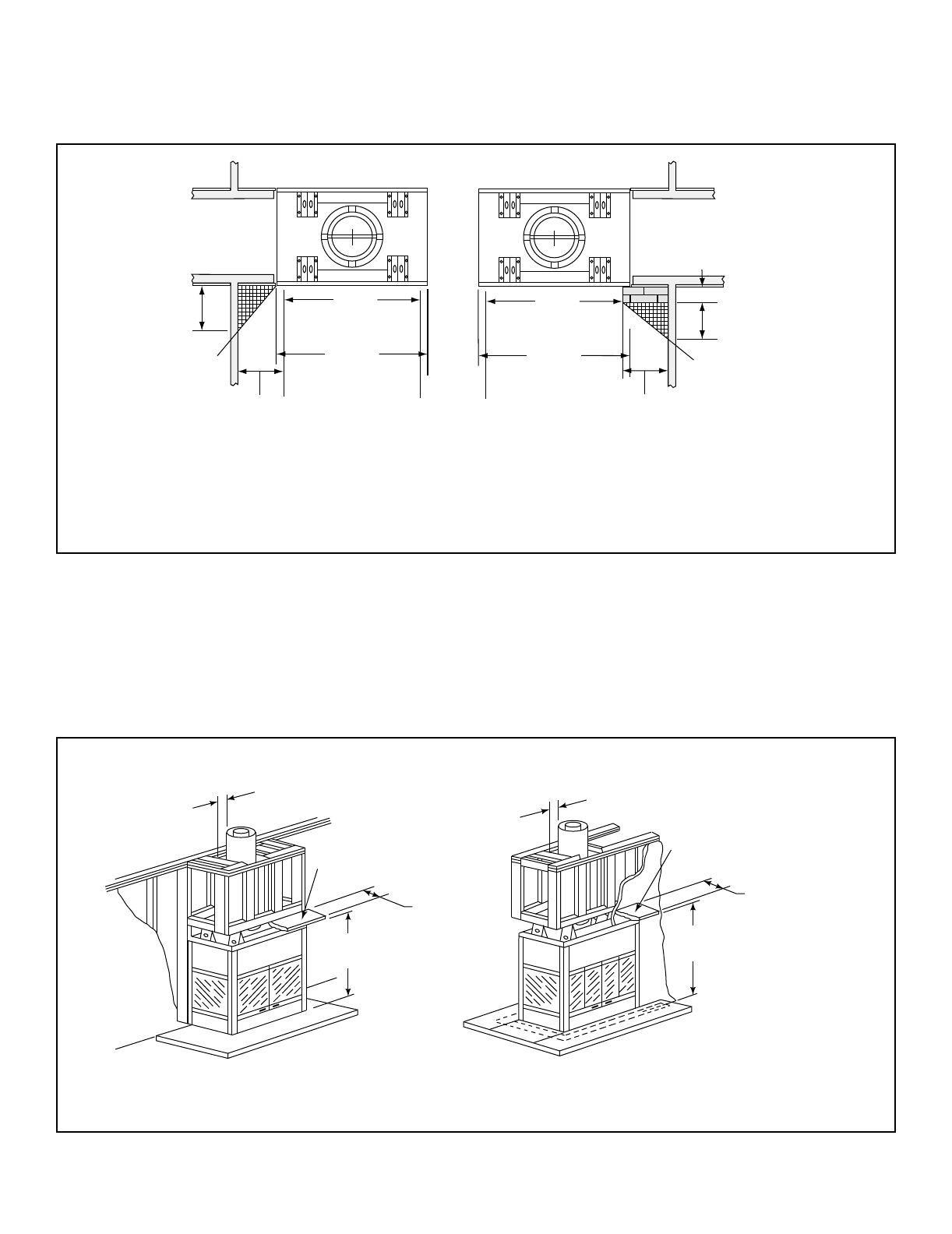
D. Frame the Fireplace
Figure 6.4 shows typical framing using combustible materials (2x4 lumber shown).
• Observe all required air space clearances to combustible materials as shown in Figure 6.1 & 6.2.
• Framing across the top of replace must be above top standoffs.
Figure 6.4 Framing the Fireplace
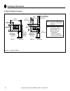
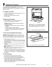
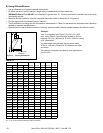
C. Sidewalls/Surrounds
• Adjacent combustible sidewalls must be located a minimum of 12 in. (305 mm) from the replace opening.
• Combustible and non-combustible mantel legs, surrounds and stub walls may be constructed within the gridded area,
Figure 6.3.
Figure 6.3 Mantel Leg or Wall Projections
Heat & Glo • BAY-40, PIER-40 • 34977 • Rev AB 7/12