


20
40 in.
[1016 mm]
36 in.
[914 mm]
12 in.
[305 mm]
9 3/4 in.
[248 mm]
12 in.
[305 mm]
12 in.
[305 mm]
Grid represents 1 in. (25 mm) squares
FLUSH
FRONT
4 in.
[102 mm]
BRICK
FRONT
50° angle
39° angle
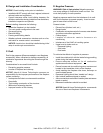
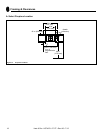
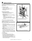
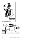
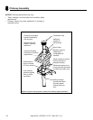
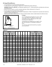
D. Frame the Fireplace
Figure 6.4 shows typical framing using combustible materials (2x4 lumber shown).
• Observe all required air space clearances to combustible materials as shown in Figure 6.1 & 6.2.
• Framing across the top of replace must be above top standoffs.
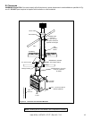
You must maintain
2 in. (51 mm) min. air space
clearance from the
chimney to the
enclosure.
23 in.
(584 mm)
Note: Fireplace
Header cannot be
positioned until after
the fireplace assembly
is in place.
41 in.
(1041 mm)
Figure 6.4 Framing the Fireplace
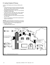
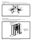
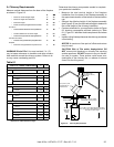
C. Sidewalls/Surrounds
• Adjacent combustible sidewalls must be located a minimum of 12 in. (305 mm) from the replace opening.
• Combustible and non-combustible mantel legs, surrounds and stub walls may be constructed within the gridded area,
Figure 6.3.
Figure 6.3 Mantel Leg or Wall Projections (Acceptable on both sides of opening)
Heat & Glo • HST-42D • 27177 • Rev AG • 7/12