


Heat & Glo • FB-IN-S, FB-GRAND-S • 783-910 Rev. D • 3/08
19
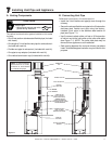
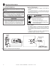
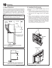
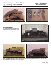
A. Mantel Projections
Figure 10.1 shows the minimum vertical and corresponding
maximum horizontal dimensions of appliance mantels or
other combustible projections above the top front edge
of the appliance, not the surround. See Figure 10.2
for required clearances when using Halston or Galleria
Doors.
10
10
Finishing
Figure 10.1 Clearances to Mantels or other Combustibles
above Appliance
MEASUREMENTS FROM
TOP EDGE OF UNIT
12 in. MIN.
12 in. MAX.
MANTEL
EXHAUST
VENT PIPE
INLET AIR
VENT PIPE
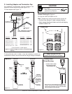
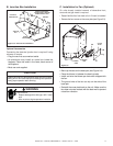
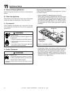
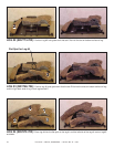
B. Installing Trim Surrounds
Combustible materials MUST NEVER overlap onto the
front face.
1. Find the coiled low voltage wires and ON/OFF switch at-
tached to outer right side of the insert (see Figure 10.2).
2. Reconnect the low voltage wires to the ON/OFF
switch.
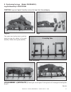
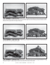
3. Attach surround assembly by hooking the support
bracket on the locating tabs on top of the gas insert
fi replace (see Figure 10.2.) Once the surround assem-
bly is on the locating tabs, ensure the bottom hooks
are resting on the locating pins at the base. Reposition
the fi replace if necessary. Refer to surround instruc-
tions provided with the decorative surround.
Figure 10.3 Trim Surround Installation
FIREBOX
LOCATING SLOTS
LOCATING TABS
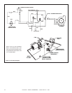
12 IN. MAX.
MANTEL
15 IN. MIN.
TOP OF DOOR
Figure 10.2 Clearances to Mantels or other Combustibles above
Appliance when using Galleria or Halston Doors
Note: When using Galleria or Halston Doors with FB-
GRAND-S and FB-IN-S, a 15 inch minimum vertical distance
from top of door to bottom of mantel is required.