


18
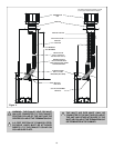
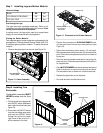
Step 2. Positioning, Leveling, and
Securing the Insert
• Place the insert into position.
• Level the insert from side to side and from front to back.
Use the leveling legs included with the manual
bag if necessary to set each corner of the base.
!
!
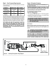
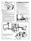
Step 3. The Gas Control System
WARNING: THIS UNIT IS NOT FOR USE WITH
SOLID FUEL.
These models use a standing pilot ignition type of gas con-
trol system.
Standing Pilot Ignition System
This system includes millivolt control valve, standing pilot,
thermopile/thermocouple flame sensor, and piezo ignitor.
WARNING: 110-120 VAC MUST NEVER BE
CONNECTED TO A CONTROL VALVE IN A
MILLIVOLT SYSTEM.
STANDING PILOT
Figure 6. Gas Controls System
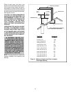
Step 4. The Gas Supply Line
NOTE: Have the gas supply line installed in accordance
with local building codes by a qualified installer
approved and/or licensed as required by the locality.
(In the state of Massachusetts installation must be
performed by a licensed plumber or gas fitter).
NOTE: Before the first firing of the fireplace, the gas
supply line should be purged of any trapped air.
NOTE: Consult local building codes to properly size
the gas supply line leading to the 1/2 inch (13 mm)
hook-up at the unit.
This gas fireplace is designed to accept a 1/2 inch
(13 mm) gas supply line. To install the gas supply line:
• A listed (and State of Massachusetts approved) 1/2 inch
(13mm) tee-handle manual shut-off valve and a listed
flexible gas connector are connected to the 1/2 inch
(13mm) inlet of the control valve. NOTE: If substituting
for these components, please consult local codes for
compliance.
• Locate the gas line access hole in the outer casing of
the fireplace.
• Open the lower grille, insert the gas supply line through
the gas line hole, and connect it to the shut-off valve.
• When attaching the pipe, support the control so that the
lines are not bent or torn.
• After the gas line installation is complete, use a soap
solution to carefully check all gas connections for leaks.
WARNING: DO NOT USE AN OPEN FLAME
TO CHECK FOR GAS LEAKS.
!
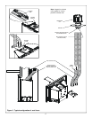
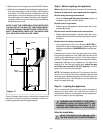
Figure 7. Gas Supply Line
Remote Control
The receiver for the remotes must be installed BETWEEN
the base pan of the insert and the firebox of the wood-burn-
ing fireplace (see photo below).
EXISTING BOTTOM
OF FIREPLACE
REMOTE
RECEIVER
UNIT
EXISTING SIDE
REFRACTORY
GAS
SHUT-OFF
FLEXIBLE
GAS LINE
CONTROLS