


Heat & Glo • EXCLAIM-36C Woodburning Fireplace • 4013-093 Rev G • 08/06
27
B. Finishing Material
• Combustible Material
Material which is made of or surfaced with wood,
compressed paper, plant fi bers, plastics, or any material
capable of igniting and burning, whether fl ame proofed or
not, plastered or not plastered.
• Non-Combustible Material
Material which will not ignite and burn. Such materials are
those consisting entirely of steel, iron, brick, tile, concrete,
slate, glass or plasters, or any combination thereof.
Materials that are reported as passing ASTM E 136,
Standard Test Method for Behavior of Materials in a
Vertical Tube Furnace at 750° C, shall be considered
non-combustible materials.
• Non-Combustible Sealant Material
Sealants which will not ignite and burn: Rutland, Inc.
Fireplace Mortar #63 (or equivalent).
After completing the framing and applying the facing material
(drywall) over the framing, a bead of non-combustible seal-
ant must be used to close off any gaps at the top and sides
between the fi replace and facing to prevent cold air leaks.
Large gaps can be bridged with fi berglass rope gasket.
Only non-combustible materials may be used to cover the
metal fi replace front.
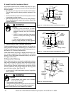
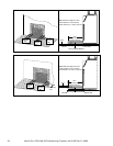
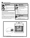
D. Sidewalls/Surrounds
Adjacent combustible side walls must be located a minimum
of 12 in. (305 mm) from the fi replace opening. If you are us-
ing a decorative surround constructed of combustible ma-
terial, it must be located within the shaded area defi ned in
Figure 8.7. Short stub walls are also acceptable if they are
contained within the shaded area.
E. Glass Doors
This fi replace has been tested and listed for use with doors
as specifi ed in Section 12.B. Fireplace Components. Please
refer to the manual packed with each set of doors for instal-
lation instructions.
12 in.
(305 mm)
Min.
12 in. (305 mm)
Max.
Top of
Fireplace
Opening
Mantel
1-1/2 in. (38 mm) max.
6 in. (152 mm) Min.
Header
Standoff
Gas Knockout
Standoff
23-3/4 in.
(603 mm)
50°
12 in.
(305 mm)
36 in.
(914 mm)
(opening)
45-1/2 in.
(1156 mm)
(framing)
39°
4 in.
(102 mm)
BRICK
FRONT
FLUSH FRONT
12 in.
(305 mm)
19-3/4 in.
(502 mm)
Figure 8.7 Sidewalls/Surrounds
Fire Risk
• Use only non-combustible material below
standoffs.
• Material such as cement board is
acceptable.
WARNING
Fire Risk
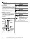
Do NOT obstruct air inlet or outlet grilles.
Finishing materials must not interfere with:
• Air fl ow
• Operation of doors
• Access for service
WARNING
Fire Risk
Finish all edges and fronts to clearances and
specifi cations.
• Metal fi replace front may be covered with
non-combustible material only.
• Do NOT overlap combustible materials onto
fi replace front.
• Install combustible materials up to specifi ed
clearances on top front and side edges.
• Seal joints between the fi nished wall and
fi replace top and sides using only a 300° F
minimum sealant.
WARNING
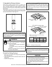
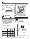
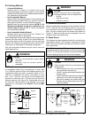
C. Mantel
A combustible mantel may be positioned no lower than
12 in. (305 mm) above the top of the fi replace opening. The
combustible mantel may have a maximum depth of 12 in.
(305 mm). Combustible trim pieces that project no more
than 1-1/2 in. (38 mm) from the face of the fi replace can
be placed no closer than 6 in. (152 mm) from the top of the
fi replace opening. See Figure 8.6. Combustible trim must
not cover the metal surfaces of the fi replace. This mantel
clearance is in accordance with Section 7-3.3.3 of ANSI/
NFPA211.
Figure 8.6 Mantel Specifi cations
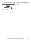
Note: The frame of the AED door overlaps the front of the
fi replace beyond the opening by 3/4 in. (19 mm) on each side
and 1-1/2 in. (38 mm) above the top. This should be allowed
for when applying facing to the front of the fi replace.