


25
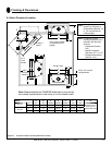
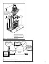
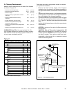
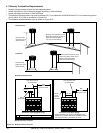
A. Chimney Requirements
Measure vertical distances from the base of the fi replace
as shown in Figure 8.2.
20 ft (6.10 m) max.
pipe between an
offset & return
Ceiling firestop
35 ft (10.7 m)
max. straight
unsupported
chimney height
16.5 ft (5.03 m) min. height/single offset-return
20 ft. (6.10 m) min. height/double offset-return
90 ft (27.4 m) max. height
6 ft (1.83 m) max.
unsupported chimney
above roof
41-1/4 in.
(1048 mm)
Effective
Height
Figure 8.2 Chimney Requirements
Table 8.1
• Minimum overall straight height 16.5 ft (5.03 m)
• Minimum height with offset/return 16.5 ft (5.03 m)
• Maximum height 90 ft (27.43 m)
• Maximum chimney length between an offset
and return
20 ft (6.1 m)
• Maximum distance between chimney
stabilizers
35 ft (10.67 m)
• Double offset/return minimum height 20 ft (6.1 m)
• Maximum unsupported chimney length
between the offset and return
6 ft (1.83 m)
• Maximum unsupported chimney height above
the fi replace
35 ft (10.67 m)
• Maximum unsupported chimney above roof 6 ft (1.83 m)
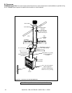
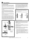
WARNING! Risk of Fire! You must maintain 2 in. (51
mm) air space clearance to insulation and other combus-
tible materials around the chimney system. Failure to do
so may cause overheating and fi re.
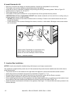
Determine the chimney components needed to complete
your particular installation:
• Measure the total vertical height of the fireplace
installation from the base of the fi replace assembly to
the approximate location of the bottom of the termination
cap.
• Subtract the effective height of the fi replace assembly
(see Figure 8.2) from the total vertical height to determine
the overall height of the chimney installation.
• Create a schematic for your application similar to Figure
8.2 showing components required (referring to Table
8.1). Figure 8.1 identifi es those components and where
used.
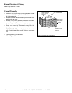
• Install a ceiling fi restop whenever the chimney penetrates
a fl oor/ceiling.
NOTICE: A maximum of two pairs of offsets and returns
may be used.
CAUTION! Risk of Fire and/or Asphyxiation! DO
NOT connect this fi replace to a chimney fl ue servicing
another appliance. DO NOT connect to any air distribu-
tion duct or system. These actions could cause over-
heating/fi re in the chimney fl ue, or release of exhaust
fumes into the living areas.
Heat & Glo • EM-415, EM-485 • 33056 • Rev V • 05/08
HEIGHT OF CHIMNEY COMPONENTS in. mm
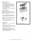
Chimney Stabilizer
SL3 4-3/4 121
Ceiling Firestops
FS338 0 0
FS339 0 0
FS340 0 0
Offsets/Returns
SL315 13-3/8 340
SL330 15-1/2 394
Roof Flashing
RF370 0 0
RF371 0 0
Chimney Sections*
SL306 4-3/4 121
SL312 10-3/4 273
SL318 16-3/4 425
SL324 22-3/4 578
SL336 34-3/4 883
SL348 46-3/4 1187
* Dimensions refl ect effective height.