


22
Step 9. Before Lighting the Appliance
Before lighting the appliance, be sure to do the following:
Remove all paperwork from underneath the fireplace.
Review safety warnings and cautions
• Read the Safety and Warning Information section at
the beginning of this Installers Guide.
Double-check for gas leaks
• Before lighting the appliance, double-check the unit for
possible gas leaks.
Double-check vent terminations for obstructions.
• Before lighting the appliance, double-check the unit for
possible obstructions that could be blocking the vent ter-
minations.
Double-check for faulty components
• Any component that is found to be faulty MUST BE re-
placed with an approved component. Tampering with the
appliance components is DANGEROUS and voids all war-
ranties.
A small amount of air will be in the gas supply lines. When
first lighting the appliance, it will take a few minutes for the
lines to purge themselves of this air. Once the purging is
complete, the appliance will light and will operate normally.
Subsequent lightings of the fireplace will not require this
purging of air from the gas supply lines, unless the gas
valve has been turned to the OFF position, in which
case the air would have to be purged.
NOTE: The fireplace should be run 3 to 4 hours on the initial
start-up. Turn it off and let it cool completely. Remove and
clean the glass. Replace the glass and run the fireplace for
an additional 8 hours. This will help to cure the chemicals
used in the paint and logs.
Step 10. Lighting the Appliance
You’ve reviewed all safety warnings, you’ve checked the
appliance for gas leaks, you know the vent system is
unobstructed, and you’ve checked for faulty components.
Now you’re ready to light the appliance.
WARNING: PLEASE REFER TO THE USER’S
MANUAL FOR ALL CAUTIONS, SAFETY, AND
WARNING INFORMATION PERTAINING TO THE
LIGHTING AND OPERATION OF THE APPLIANCE.
After the Installation
LEAVE THIS INSTALLATION MANUAL WITH
THE APPLIANCE FOR FUTURE REFERENCE.
!
!
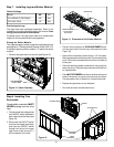
3. Reconnect the low voltage wires to the ON/OFF switch.
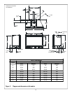
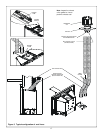
4. Attach surround assembly by hooking the support brack-
et on the locating tabs on top of the gas insert fireplace
(see Figure 14.) Once the surround assembly is on the
locating tabs, ensure the bottom hooks are resting on
the locating pins at the base. Reposition the fireplace if
necessary. Refer to surround instructions provided with
the decorative surround.
NOTE: PLACE THE THREE INSULATION PIECES INTO
THE CAVITIES AT THE BACK OF THE SURROUND BE-
FORE POSITIONING THE INSERT INTO THE FACTORY-
BUILT OR MASONRY FIREPLACE. THIS INSULATION
WILL HELP SEAL FOR COLD AIR LEAKS.
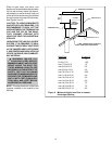
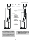
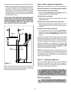
Figure 15
Figure 15 shows the minimum vertical and corresponding
maximum horizontal dimensions of mantels or other com-
bustible projections above the gas fireplace.
TOP OF
UNIT
12” MIN.
12” MAX.
MANTEL