


Heat & Glo • CFL-18/24/30-B, ST-CFL-24 • 526-900 Rev. F • 7/05
16
B. Minimum inlet gas supply pressure for purposes of
input adjustment, shall be 7.0 inches w.c. (1.75kPa)
for natural gas and 11.0 inches w.c. (2.75kPa) for pro-
pane (LP gas). Maximum inlet gas supply pressure
shall be 14.0 in. w.c. (3.5kPa) for both natural gas and
propane (LP gas). Manifold (outlet) pressure should
be 3.5 inches w.c. (.87kPa) for natural gas and 10.0
inches w.c. (2.5kPa) for LP gas.
C. The appliance and its individual shut off valve must
be disconnected from the gas supply piping system
during any pressure testing of the system at test pres-
sures in excess of 1/2 psig (3.5kPa).
D. This appliance must be isolated from the gas sup-
ply piping system by closing its individual manual shut
off valve during any pressure testing of the gas supply
piping system at test pressures equal to or less than
1/2 psig (3.5kPa).
E. NOTE: THE GAS SUPPLY LINE SHOULD BE
PURGED OF ANY TRAPPED AIR PRIOR TO THE
FIRST FIRING OF THE UNIT.
F. CAUTION: During the initial purging and sub-
sequent lightings, NEVER allow the gas control
valve knob to remain depressed in the "PILOT" po-
sition without pushing the red ignitor button at least
once every second.
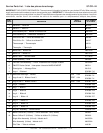
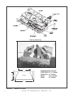
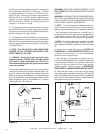
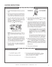
G. A damper stop clamp with set screw is provided to
prevent full closure of the fireplace damper blade. At-
tach the clamp to the edge of the damper blade with
pliers or wrenches. If the damper stop supplied does
not fit the application, use a permanent means that will
keep the damper open to a MINIMUM of 51 square
inches (328cm
2
). See Figure 5.
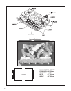
Figure 6
Figure 5
WARNING: OPEN THE CHIMNEY DAMPER TO ITS
FULLY OPEN POSITION WHEN BURNING THIS GAS
LOG SET.
WARNING: LOGS MUST NEVER BE BURNED WITH-
OUT THE FLUE DAMPER IN THE FULL OPEN POSI-
TION. FAILURE TO DO SO IS DANGEROUS TO YOUR
HEALTH AND VOIDS ALL WARRANTIES.
H. NOTE: The Commonwealthof Massachusetts re-
quires that the chimney flue damper, when used with
gas logs, shall be welded open or completely removed.
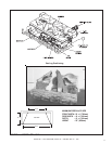
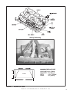
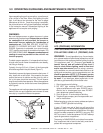
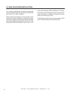
I. Your appliance control system is a millivolt type. It
consists of a pilot burner, a gas control valve/regulator,
a thermopile, a piezo ignitor, and an ON/OFF rocker
switch. See Figure 6 for control system wiring diagram.
J. NOTE: An Optional Remote Control Kit and Wall
Switch Kit , for turning the burner ON/OFF are avail-
able. Detailed installation instructions are found in each
kit.
K. Test fire the unit after referring to the SAFETY IN-
FORMATION and LIGHTING INSTRUCTIONS found
in Section 3 in this manual, or on the label plate as-
sembly found on the gas-burner.
L. After the gas line installation is complete, all con-
nections must be tightened and checked for leaks with
a commercially-available, non-corrosive leak check
solution. Be sure to rinse off all leak check solution
following testing. Refer to Section 3, OPERATING
GUIDELINES and MAINTENANCE INSTRUCTIONS.
M. Once the gas-burner is test fired and gas supply
lines are purged, assemble the grate(s) and logs. Be
certain to follow the Log Placement Instructions shipped
with your unit. Remember to keep the Log Instructions
along with this manual for future use.