


Heat & Glo • CRESTFIRE Series Electric Fireplace • 4030-239 Rev J • 04/05
9
Note: This heater must be electrically wired and grounded
in accordance with local codes or, in the absence of local
codes, with National Electric Code ANSI/NFPA 70-latest
edition or the Canadian Electric Code, CSA C2.1 as
appropriate.
All wiring must be done by a qualifi ed electrician.
Use appropriate wire to meet local and national
codes for rated power consumption.
Shock Risk
Improperly grounded outlets could cause
electrical shock.
• Always use properly grounded, fused and
polarized outlets.
• Always used ground fault protection where
required by electrical code.
WARNING
Label all wires prior to disconnection when servicing
controls. Wiring errors can cause improper and dangerous
operation. Verify proper operation after servicing.
CAUTION
Disconnect remote controls during your extended absence.
This will prevent accidental operation of the heater.
CAUTION
A. 120VAC Wall Outlet Installation
• The heater is The heater is wired from factory with a
polarized plug.
• For ease of electrical hook up, you may wish to install the
heater near an existing outlet. A 15 amp, 120 volt circuit is
required. A dedicated circuit is preferred but not essential
in all cases. A dedicated circuit will be required if, after
installation, the circuit trips or fuse blows on a regular
basis when the heater is operated. Additional appliances
on the same circuit may exceed the current rating of the
circuit breaker.
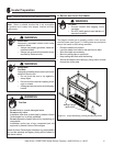
• Before plugging heater into wall outlet, make sure all
control switches are in the “OFF” position. To access
the controls, lift up on the lower grille panel and rotate it
forward.
• If the power cord is not being used, go to Step B below. If
the cord does not reach the outlet, a No. 16-AWG minimum
wire size extension cord rated for a minimum of 1875 watts
may be used.
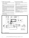
B. 120VAC Hardwire Installation
(Minimum 14 gauge two conductor wire, non-metallic
sheathing with ground.)
• Turn off circuit breaker.
• Access knockout.
• Disconnect black and white wires between the heater
and plug. Remove the power cord. Remove the electrical
knockout and install the cable clamp (not provided) onto
the hole. Remove the connectors on the wires from the
heater and strip them back 1/2 in.
• Feed 8 in. of service wire through cable clamp (not
provided) and secure.
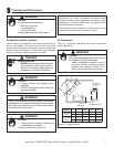
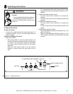
• Connect black and white wires of the heater to the
black and white wires from the service. Connect green
(ground) wire from heater to the ground of the service.
See Figure 4.1.
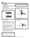
• Wall switch wiring (see below) is to be done at this time.
• Use a 4 in. cover plate (not provided) over access hole if
required.
• Remove the protective cover by cutting the tape located
on the outer perimeter.
Shock Risk
Improperly grounded outlets could cause
electrical shock.
• Always use properly grounded, fused and
polarized outlets.
• Always use ground fault protection where
required by electrical code.
WARNING
Shock Risk
Fire Risk
Improperly protected power cords could
cause electrical shock or fi re.
• Do not pinch the cord or lay against a
sharp object.
• Do not cover the cord with carpeting, throw
rugs or runners.
• Secure and arrange cord to avoid a
tripping hazard.
WARNING
Note: Follow all national and local electrical codes.
4
Wiring