


Heat & Glo • CRESTFIRE Series Electric Fireplace • 4030-239 Rev J • 04/05
10
+
-
A
A
B
B
FLAME MOTOR
THERMOSTAT
RELAY
HEAT SWITCH
OPTIONAL
BLOWER
BLOWER
HEATER1
HEATER2
240VAC
BLACK
RED
HIGH LIMIT
POWER NEUTRAL MUST NOT
CONNECT TO VIRTUAL
NEUTRAL OF HEATERS OR
BLOWER IN 240VAC VERSION
120VAC - 240VAC 60HZ SPLIT-PHASE
3 PIN
WIRING
HARNESS
WHITE
HEATER1
HIGH LIMIT
120VAC
BLACK
RED
-12VDC
120VAC PLUG or 120/240VAC HARD WIRED
120VAC 60Hz
GROUND
NEUTRAL
120VAC 60Hz
LINE1 HOT
240VAC 60Hz
LINE2 HOT
POWER
12VDC
SUPPLY
REMOTE OR
WALL ON/OFF
SWITCH
REMOTE
HEAT
CONTROL
SPEED CONTROL
-12VDC
DIMMER
120VAC
LAMPS
R2
D1
DIODE
LAMP LAMP
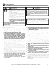
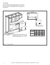
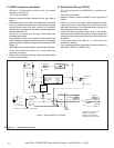
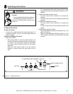
Figure 4.1 120V/240V Wiring Diagram
C. 240VAC Hardwire Installation
(Minimum 14 gauge three conductor wire, non-metallic
sheathing with ground.)
• Turn off circuit breaker.
• Remove access knockout located on the right side of
heater.
• Disconnect black and white wires between the heater
and plug. Remove the power cord. Remove the electrical
knockout and install the cable clamp (not provided).
Remove the connectors on the wires from the heater and
strip them back 1/2 in.
• Feed 8 in. of service wire through cable clamp (not
provided) and secure.
• Connect black, white and red wires of the heater to the
black, white and red wires from the service. Connect green
(ground) wire from heater to the ground of the service. See
Figure 4.1.
• Wall switch wiring (see below) is to be done at this time.
• Cover the access hole with a 4 in. cover plate (not
provided) if required.
• Remove the protective cover by cutting the tape located
on the outer perimeter.
D. Wall Switch Wiring (12VDC)
*Do not connect wires to 120/240VAC* (hardwired heat-
ers only)
• Turn off circuit breaker.
• Remove access knockout located on the right side of
heater.
• Feed 8 in. of wire for the wall switch through the cable
clamp and secure. Low voltage wire can be used for the
wall switch connection. It is recommended to only go 10 ft
from the heater to the wall switch.
• Locate the light blue (wall switch) wires in the heater.
Connect one wall switch (blue) wire to wire for switch and
connect the other wall switch (blue) wire to the other wire
for switch.
• Cover the access hole with a 4 in. cover plate (not
provided) if required.
• Run the wall switch wire to the wall box and connect to a
wall switch (WSK-21 & WSK-21-W).