


Heat & Glo • CRESTFIRE Series Electric Fireplace • 4030-781 Rev F • 10/06
10
B
+
B
A
-
A
LAMP
LAMP
FLAME M0TOR
120 VAC
LAMPS
REMOTE HEAT
CONTROL
REMOTE OR
WALL ON/OFF
SWITCH
12VDC
SUPPLY
POWER
WHITE
HEAT SWITCH
OPTIONAL
-12VDC
SPEED
CONTROL
R2
D1
DIODE
THERMOSTAT
RELAY
DIMMER
PE
N
L1
L2
120 V
120 V
240 V
TERMINAL STRIP
120 VAC PLUG OR 120/240
HARD WIRED
3 PIN WIRING
HARNESS
120 VAC
BLACK
RED
-12VDC
HIGH LIMIT
BLOWER
BLOWER
HEATER 1
240 VAC
HIGH LIMIT
BLOWER
HEATER 1
HEATER 2
BLACK
RED
POWER NEUTRAL MUST NOT
CONNECT TO VIRTUAL NEUTRAL
OF HEATERS OR BLOWER IN
240VAC VERSION
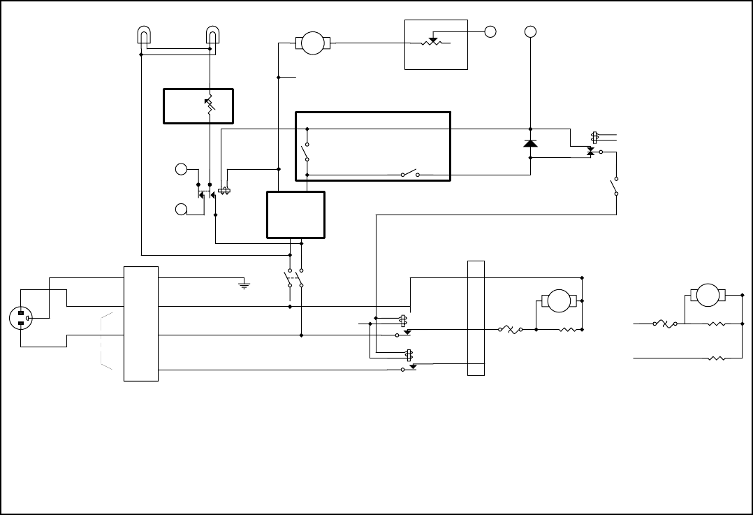
120VAC - 240VAC 60 HZ SPLIT-PHASE
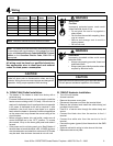
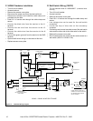
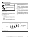
Figure 4.1 120V/240V Wiring Diagram
C. 240VAC Hardwire Installation
• Turn off circuit breaker.
• Access knockout.
• Remove the access cover plate.
• Disconnect the power cord from the terminal block.
• Remove the knockout and install the cable clamp (not
provided) into the hole.
• Feed 8 in. of service wire through the cable clamp and
secure.
• Connect the black wire from the service to the L1
terminal.
• Connect the red wire from the service to the L2
terminal.
• Connect the white wire from the service to the N
terminal.
• Connect the green (ground) from the service to the GND
terminal.
• Optional wall switch wiring is to be done at this time.
• Replace access cover plate.
D. Wall Switch Wiring (12VDC)
*Do not connect wires to 120/240VAC* (hardwired heat-
ers only)
• Turn off circuit breaker.
• Access knockout.
• Remove the access cover plate.
• Feed 16 in. of service wire through the cable clamp and
secure.
• Low voltage wire can be used for the wall switch
connection.
• Locate the loop of blue wire on the accessory
connector.
• Cut the loop and connect one side to one of the wall switch
wires and the other side to the other wire for the switch.
• Replace the access cover plate.
• Run the wall switch wire to the wall box and connect to a
wall switch (WSK-21 & WSK-21-W).