


19
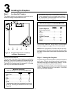
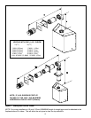
2. Continue Adding Vent Components
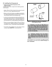
WARNING: INSTALLATION OF THE 7000XLT
FIREPLACE REQUIRES THE USE OF HEAT
SHIELD 570-290 ABOVE THE FIRST 90
0
ELBOW IN
THE VENTING SYSTEM. (HEAT SHIELD NOT RE-
QUIRED FOR 6000XLTB).
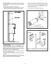
Figure 11
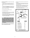
To Install the Heat Shield:
1. Determine if the heat shield is required. Do so by mea-
suring the vertical distance between the top horizontal
surface of the elbow to any combustible surface above.
If the distance is more than 4 inches, the heat shield is
NOT required. If it is 4 inches or less, the heat shield IS
REQUIRED. Install per the following steps. See Figure 11.
!
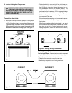
Continue adding vent components, locking each succeed-
ing component into place.
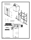
Ensure that each succeeding vent component is secure-
ly fitted and locked into the preceding component in the
vent system.
90° elbows may be installed and rotated to any point
around the preceding components vertical axis. If an el-
bow does not end up in a locked position with the pre-
ceding component, attach with a minimum of two (2)
sheet metal screws.
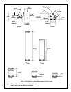
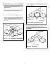
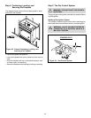
Figure 12
CORRECT INCORRECT
2. Fasten the shield in place using the four pilot holes pro-
vided in the part. The shield should be oriented such that
the 13 1/8 inch dimension (longest dimension) is run-
ning in the same direction the elbow is pointing. The
shield should be centered directly above the elbow, and
positioned so that it creates a 1/2 inch airspace between
the shield and the combustible surface. See Figure 12.
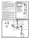
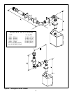
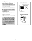
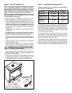
3. Install Support Brackets
For Horizontal Runs - The vent system must be supported
every five (5) feet of horizontal run by a horizontal pipe support.
To install support brackets for horizontal runs:
Place the pipe supports around the vent pipe.
Nail the pipe supports to the framing members.
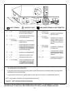
Figure 13. Adding Venting Components