


13
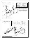
HORIZONTAL VENTING
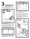
Kit No. H Max. Run
DVK-01D
DVK-01TRD 24" (610 mm)
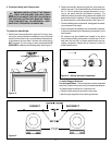
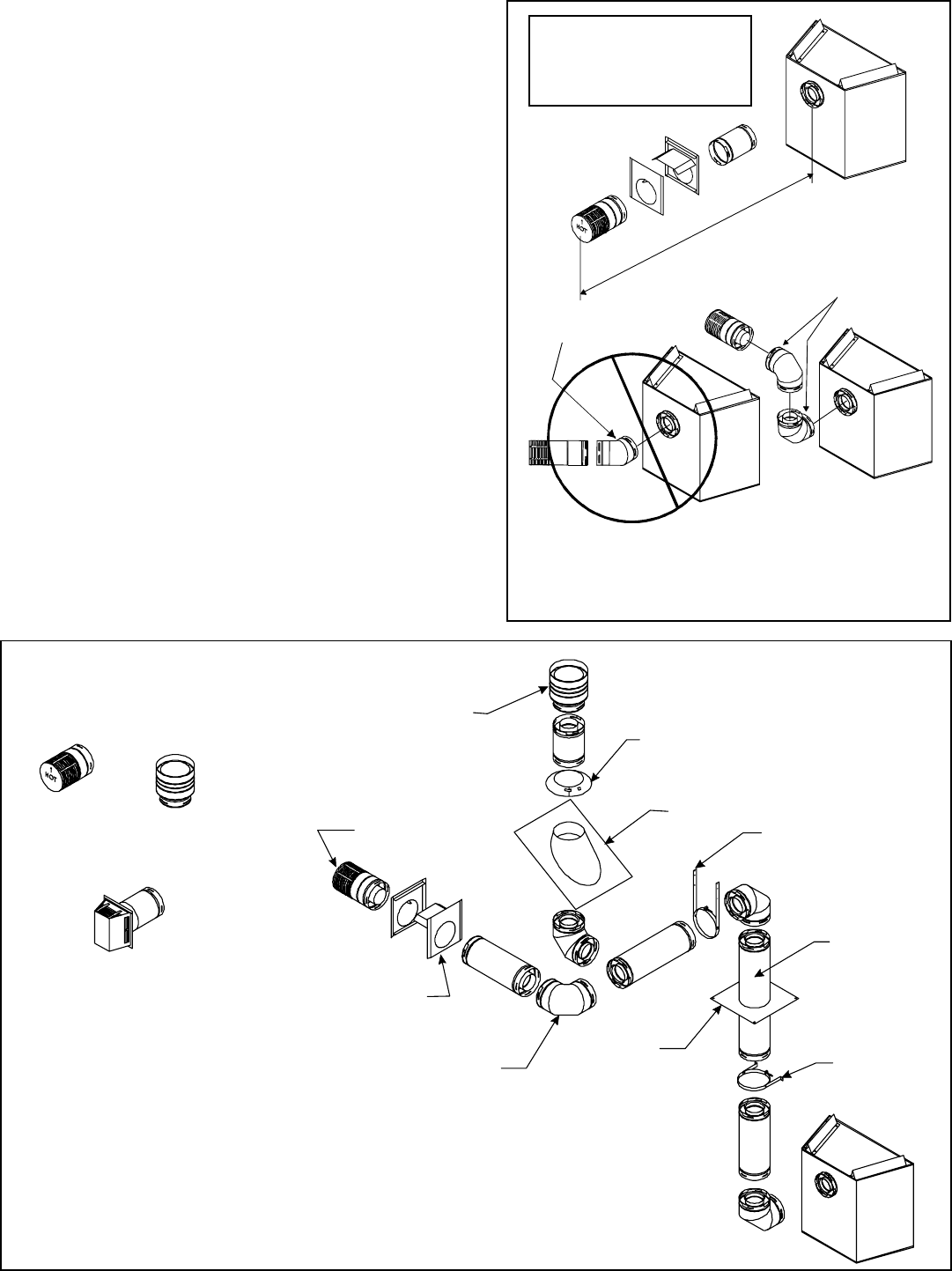
NOTE: 7000XLS & 6000XLSB models are not approved to
use 45° elbows in corner installations. Use 90° elbows.
Figure 6. Corner Installation
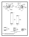
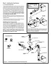
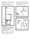
Figure 5. Vent System Components and Termination Kits
Step 3. Installing the Vent System
A. Vent System Approvals
These models are approved to use D-series direct vent pipe
components and terminations (see Figures 4 and 5). Ap-
proved vent system components are labeled for identifica-
tion. This pipe is tested and listed as an approved compo-
nent of the fireplace. The pipe is tested to be run inside an
enclosed wall. There is no requirement for inspection open-
ings at each joint within the wall. There is no required pitch
for horizontal vent runs. NO OTHER VENTING SYSTEMS
OR COMPONENTS MAY BE USED.
Detailed installation instructions are included with each vent
termination kit and should be used in conjunction with this
Installers Guide.
The flame and ember appearance may vary based on the type
of fuel burned and the venting configuration used.
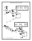
Identifying Vent Components
The vent systems installed on this gas fireplace may in-
clude one, two, or three 90°
elbow assemblies. The rela-
tionships of vertical rise to horizontal run in vent configura-
tions using 90° elbows MUST BE strictly adhered to. The
rise to run relationships are shown in the venting drawings
and tables. Refer to the diagrams on the next several pages.
NOTE: Two 45° elbows may be used in place of one
90° elbow. Rise to run ratios in the vent system must
be followed if 45° elbows are used.
HORIZONTAL
TERMINATION
WALL FIRESTOP
90 DEGREE
ELBOW
VERTICAL
TERMINATION
STORM COLLAR
ROOF FLASHING
HORIZONTAL PIPE
SUPPORT
PIPE LENGTH
WALL BRACKET
CEILING
FIRESTOP
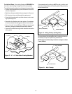
DVK-01D
DVK-TVCD
DVK-01TRD
Terminations Kits
45-DEGREE
ELBOW
90-DEGREE
ELBOWS
H