


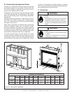
Heat & Glo • 6000G, 6000G-IPI • 2103-900 Rev. M • 9/0816
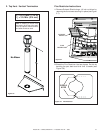
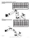
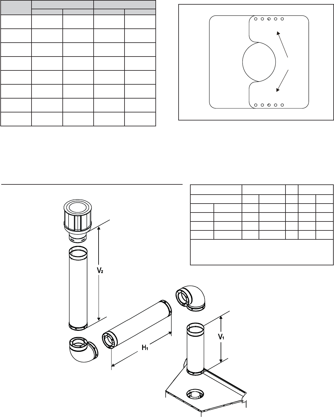
Figure 5.11
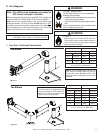
Two Elbows
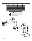
Figure 5.10
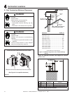
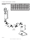
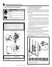
4. Center the Flue Restrictor on vent and secure in place
by using two self-tapping screws (see Figure 5.10).
5. Reinstall the Exhaust Shield.
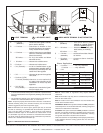
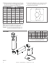
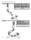
3. Match the amount of vertical you have in the sys-
tem with the chart to fi nd the appropriate position
to set the Flue Restrictor (see Figure 5.9 ).
Figure 5.9
1 2 3 4 5
SETTINGS
1 2 3 4 5
Vertical
TOP VENT REAR VENT
NG LP NG LP
4 ft. 1-1
No
Restrictor
No
Restrictor
No
Restrictor
8 ft. 2-2 1-2 1-1
No
Restrictor
15 ft. 3-3 3-2 2-2 1-2
20 ft. 3-4 3-3 3-3 2-3
25 ft. 3-4 3-3 3-3 2-3
30 ft. 4-4 3-4 3-4 3-3
35 ft. 4-4 3-4 3-4 3-3
40 ft. 5-4 4-4 4-4 3-4
Note: If the DVP-2SL adapter and SLP pipe is used, you
MUST subtract one number from the table above.
Example: Top vent 40 ft vertical with DVP pipe = 5-4
Top vent 40 ft vertical with SLP pipe = 4-3
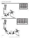
V
1
H
1
Maximum V
2
V
1
+ V
2
Min.
Elbow only 2 ft. 610 mm * * *
6 in. 152 mm 6 ft. 1.8 m * * *
2 ft. 610 mm 11 ft. 3.4 m * * *
3 ft. 914 mm 16 ft. 4.9 m * * *
4 ft. 1.2 m 20 ft 6.1 m * * *
V
1
+ V
2
+ H
1
= 50 ft (15.2 m) Maximum
*No specifi c restrictions on this value EXCEPT
V
1
+ V
2
+ H
1
cannot exceed 50 ft (15.2 m)