18
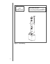
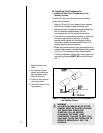
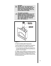
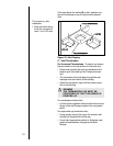
WARNING
ENSURE THAT THE FIBERGLASS
ROPE GASKET SUPPLIED WITH THE
FIREPLACE SEALS BETWEEN THE
FIRST VENT COMPONENT AND THE
OUTER FIREPLACE WRAP.
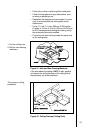
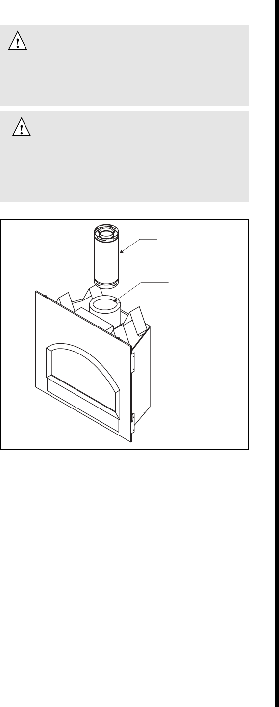
FOR MODEL 6000ARCH:
WARNNG: MAKE CERTAIN THAT THE
FIBERGLASS INSULATION BAND IS
PACKED INTO THE SPACE BETWEEN
THE 11-INCH DIAMETER TOP PIPE
HEAT SHIELD AND THE STARTER
PIPE. SEE FIGURE 16.
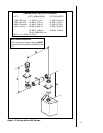
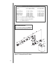
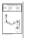
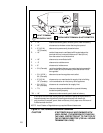
Figure 16.
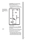
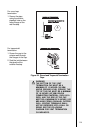
2. Continue Adding Vent Components
To continue adding vent components in accordance
with the pre-planned vent system configuration:
• Ensure that each succeeding vent component is
securely fitted and locked into the preceding com-
ponent in the vent system.
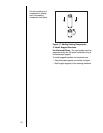
90° elbows may be installed and rotated to any point
around the preceding component’s vertical axis. If an
elbow does not end up in a locked position with the
preceding component, attach with a minimum of two
(2) sheet metal screws.
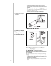
FIRST VENT
COMPONENT
FIRST VENT
COMPONENT
FIBERGLASS
INSULATION
FIBERGLASS
INSULATION


