


Heat & Glo • 350TRSI-AUF, 350TRSILP-AUF • 2089-980 Rev. o • 6/12
30
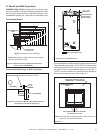
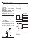
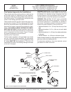
Top Vent - Vertical Termination
This model is approved to use DVP or SLP Series ue
pipe components. A DVP-TVHW or SLP-TVHW vertical
Termination Cap must be used to terminate ue systems
in a vertical position.
Approved ue system components are labeled for identi-
cation. NO OTHER FLUE SYSTEMS OR COMPONENTS
MAY BE USED. Detailed installation instructions are in-
cluded with each ue termination kit and should be used
in conjunction with this manual.
WARNING! Risk of Fire! This gas appliance and ue
assembly must be ued directly to the outside and must
never be attached to a chimney serving a separate solid
fuel burning appliance. Each gas appliance must use a
separate ue system-common ue systems are prohibited.
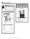
WARNING! Risk of Fire! DO NOT apply combustible
materials beyond the minimum clearances. Comply with
all minimum clearances to combustibles as specied in
this manual. Overlapping material could ignite and will in-
terfere with proper operation of doors and louvers.
• Horizontal sections 3 in. (76 mm) from the top of the
pipe.
• Horizontal sections 2-1/2 in. (64 mm) at wall shield
restops.
• Horizontal sections 1 in. (25 mm) from sides and bottom
of the pipe.
• Vertical sections 1 in. (25 mm) on all sides of pipe.
Failure to keep insulation or other material away from vent
pipe may cause over heating and re.
For alternative installations, other than depicted, contact
your dealer for further information.
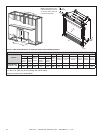
MODEL FLUE TERMINATION APPROVALS
350TRSI-AUF
350TRSILP-AUF
SLP-TVHW, DVP-TVHW
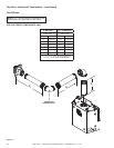
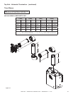
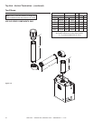
Figure 7.8
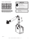
Figure 7.7
V
MAX. RUN
36 ft.
(10.97 m)
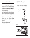
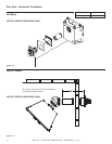
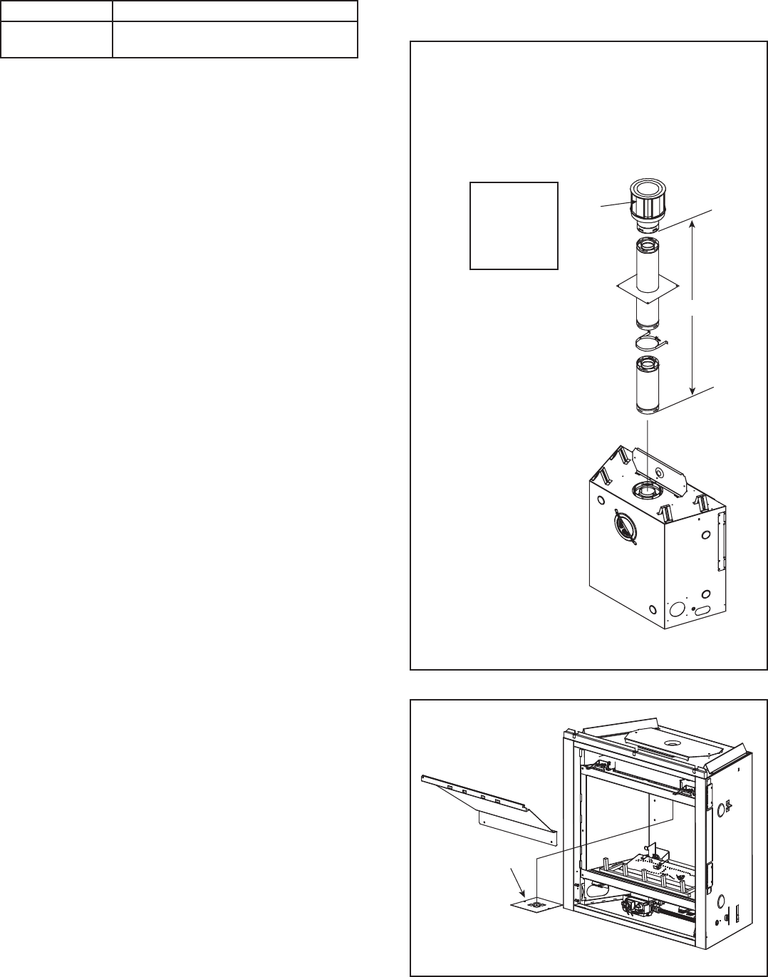
Straight Up Vertical Flue System
Figure 7.7 shows straight up vertical ue system approved
for use on this model.
If the heater installation requires a vertical ue
exceeding 14-3/4 in. (4.5 m) above the unit
with no horizontal ue or elbows a vertical ue
restrictor must be installed (see Figure 7.7).
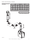
CAP
V
1
RESTRICTOR
PLATE