


5
Connecting Refrigerant Tubing Between the Indoor
& Outdoor Unit
CAUTION:
This system uses R-22 refrigerant which may
contain POE oil. When servicing, cover or seal
openings to minimize the exposure of the
refrigerant system to air to prevent accumulation
of moisture and other contaminants. See page
8 for additional info.
After outdoor and indoor unit placement has been
determined, route refrigerant tubing between the
equipment in accordance with sound installation practices.
• Whenconnecting refrigerant linesets together, it is
recommended that dry nitrogen be flowing through
the joints during brazing to prevent internal oxidation
and scaling.
• Refrigeranttubingshouldberoutedinamannerthat
minimizes the length of tubing and the number of bends
in the tubing. If precise forming of refrigerant lines is
required, a copper tubing bender is recommended.
Avoid sharp bends and contact of the refrigerant lines
with metal surfaces.
• Refrigeranttubingshouldbesupportedinamanner
that the tubing will not vibrate or abrade during system
operation.
• Tubingshouldbekeptcleanofforeigndebrisduring
installation.
• Everyeffortshouldbemadebytheinstallertoensure
that the field installed refrigerant containing components
of the system have been installed in accordance with
these instructions and sound installation practices to
insure reliable system operation and longevity.
• The maximum recommended interconnecting
refrigerant line lengths is 75 ft. and the vertical elevation
difference between the indoor and outdoor sections
should not exceed 20 ft.
ELECTRICAL WIRING
WARNING:
To avoid risk of electrical shock, personal
injury, or death, disconnect all electrical power
to the unit before performing any maintenance
or service. The unit may have more than one
electrical supply.
Label all wires prior to disconnection when
servicing the unit. Wiring errors can cause
improper and dangerous operation.
• Allelectricalconnectionsmustbeincompliancewith
all applicable local codes and ordinances, and with
the current revision of the National Electric Code
(ANSI/NFPA 70).
• ForCanadianinstallationstheelectricalconnections
and grounding shall comply with the current Canadian
Electrical Code (CSA C22.1 and/or local codes).
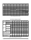
Pre-Electrical Checklist
√ Verify that the voltage, frequency, and phase of the
supply source match the specifications on the unit
rating plate. See Table 11 (page 16).
√ Verify that the service provided by the utility is sufficient
to handle the additional load imposed by this equipment.
Refer to the unit wiring label for proper voltage wiring.
√ Verify factory wiring is in accordance with the unit
wiring diagram (Figure 11, page 17). Inspect for loose
connections.
Line Voltage
• Awiringdiagramislocatedontheinsidecoverofthe
electrical box of the outdoor unit. The installer should
become familiar with the wiring diagram before making
any electrical connections to the outdoor unit.
• An electrical disconnect must be located within
sight of and readily accessible to the unit. This
switch shall be capable of electrically de-energizing
the outdoor unit.
• Linevoltage tothe unit should besupplied from a
dedicated branch circuit containing the correct fuse
or circuit breaker for the unit. Incoming field wiring
and minimum size of electrical conductors and circuit
protection must be in compliance with information listed
on the outdoor unit data label. Any other wiring methods
must be acceptable to authority having jurisdiction.
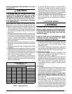
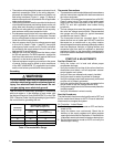
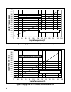
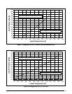
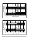
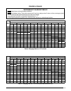
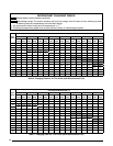
COPPER WIRE SIZE — AWG
(1% Voltage Drop)
Supply Wire Length-Feet
Supply Circuit
Ampacity
200 150 100 50
6 8 10 14 15
4 6 8 12 20
4 6 8 10 25
4 4 6 10 30
3 4 6 8 35
3 4 6 8 40
2 3 4 6 45
2 3 4 6 50
2 3 4 6 55
1 2 3 4 60
NOTE: Wire Size based on N.E.C. for 60° type copper conductors.
Table 1. Copper Wire Size
• Tomaintaintheunit'swarranty,itisrequiredthata
filter drier be installed when the system is open to
the atmosphere. This includes, but is not limited to,
replacing the evaporator and/or condenser of a system.
The filter drier must be installed in strict accordance
with the manufacturer’s installation instructions.
• Optional equipment such as liquid line solenoid
valves, low ambient, etc., should be installed in
strict accordance with the manufacturer’s installation
instructions.