


18 Wall Mounted Multi-Zone Split System Air Conditioner
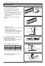
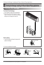
Connecting the Cable between Indoor Unit and Outdoor Unit
Connecting the Cable between Indoor Unit and Outdoor Unit
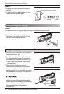
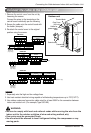
Connect the cable to the indoor unit by connecting the wires to the terminals on the control
board individually according to the outdoor unit connection. (Ensure that the color of the wires
of the outdoor unit and the terminal No. are the same as those of the indoor unit.)
The ground wire should be longer than the common wires.
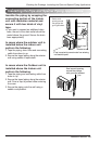
The circuit diagram is subject to change without notice.
When installing, refer to the electrical diagram behind the front panel of Indoor Unit.
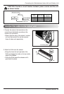
The wiring for the outdoor unit can be found on the inside of the Outdoor Unit control cover.
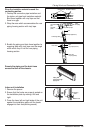
Connect the cable to the Indoor unit
RECOMMENDATION:
• The circuit diagram is subject to change without notice.
• Be sure to connect wires according to the wiring diagram.
• Connect the wires firmly, so that they can not be pulled out easily.
• Connect the wires according to color codes by referring to the wiring diagram.
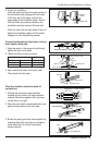
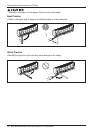
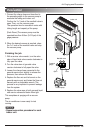
RECOMMENDATION:
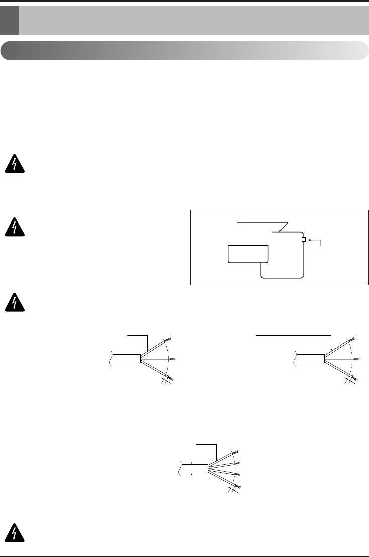
Provide a
circuit breaker between power
source and the outdoor unit as
shown below.
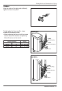
RECOMMENDATION:
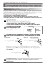
The power cord connected to the outdoor unit should
comply with the following specifications: ETL recognized and CSA certified.
The power connecting cable connected to the indoor and outdoor unit
should be comply with the following specifications: ETL recognized and
CSA certified.
Air
Conditioner
Main power source
Circuit Breaker
Use a circuit breaker
or time delay fuse.
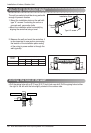
GN/YL
20 mm
(0.79 inch)
Line voltage (208~230V)
18 / 24K BTU/h 36K BTU/h
GN/YL
20 mm
(0.79 inch)
Line voltage (208~230V)
AWG14
AWG12 (Allowable temperature
to the wire rated at least 90C˚)
GN/YL
20 mm
(0.79 inch)
AWG18
Low voltage (below 40V)
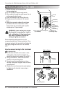
RECOMMENDATION: When using the separate wires as the power cord, please secure
the separate wires into the control box panel using tie wraps to hold all wires
together in place.