


12
CAUTION:
Isolation must be maintained from the external
Class 2 output of any transformer in a cooling
circuit. Use a thermostat with isolating contacts
to prevent inter-connection of Class 2 outputs.
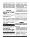
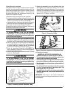
• Thethermostatshouldbemountedabout5feetabove
the floor on an inside wall. DO NOT install the thermostat
on an outside wall or any other location where its
operation may be adversely affected by radiant heat from
fireplaces, sunlight, or lighting fixtures, and convective
heat from warm air registers or electrical appliances.
Refer to the thermostat manufacturer’s instruction sheet
for detailed mounting and installation information.
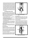
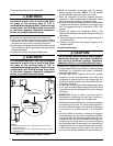
• Installthegrommet,whichispackedwiththeunit,in
the hole for low-voltage wires. Properly connect the
low-voltage wiring between the thermostat, outdoor
unit, and control board. NOTE: When the low voltage
wires are positioned in this grommet, the grommet will
prevent chafing and/or shorting of the low voltage leads.
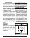
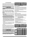
Control Board
The control board in the air handler controls the timing
sequence of the elements. The board is equipped with a 3
second blower on delay and a 15 second blower off delay
in heating and a 40 second blower off delay in cooling.
See Figures 14 or 15 (page 23) and Table 12 (pages 29-
31) for control board modes and actions.
Twinning
HMG**F1E series air handler’s are not supplied with a
built in twinning capability. To connect two air handlers to a
common single stage AC condensing unit or heat pump, a
twinning kit is available for field installation. Please follow
the instructions supplied with the kit.
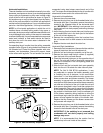
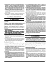
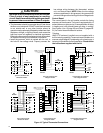
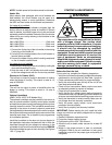
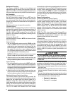
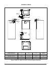
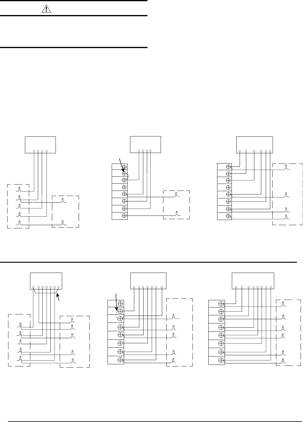
Figure 10. Typical Thermostat Connections
G
R
C
W/EO
Y
Thermostat
G
R
W
Thermostat
Y
C
Y
G
R
W
Thermostat
Y
C
Air
Handler
Air
Conditioner
Y
Typical Air Conditioner with
Standard Air Handler
GRC
E
O
Y
Thermostat
Typical Heat Pump with
Standard Air Handler
Typical Air Conditioner with
2-Stage Air Handler
Typical Heat Pump with
2-Stage Air Handler
G
R
W2
C
O
Y1
Thermostat
O
Y1
R
C
G
R
W/E
Thermostat
Y1
C
Y1
W2
Typical 2-Stage Air Conditioner
with 2-Stage Air Handler
Typical 2-Stage Heat Pump with
2-Stage Air Handler
Y2
Y2
Y2
Y2 OUT
W/E
R
Air
Conditioner
Air
Handler
Air
Conditioner
Air
Handler
Heat Pump
Air
Handler
Heat Pump
O
R
C
Y
Air
Handler
Heat Pump
NOTE: Jumper between
W2 & E is required when
no OD T-Stat is used.
W1
Y
G
R
C
NOTE: Jumper W1 & W2
together if not using W2
on thermostat
Y1
W2
W1
O
Y/Y2
G
R
C
Y1
W2
W1
O
Y/Y2
G
R
C
W2
Air
Handler
W1
Y
G
R
C
R
C
Y
W2
O
Y1
W2
W1
O
Y/Y2
G
R
C
Y1
W2
W1
O
Y/Y2
G
R
C
W2
W2
W2
NOTE: Jumper W1 & W2
together if not using W2
on thermostat