


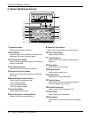
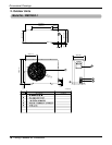
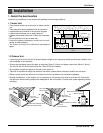
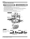
20 Ceiling Cassette Air Conditioner
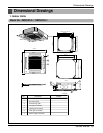
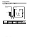
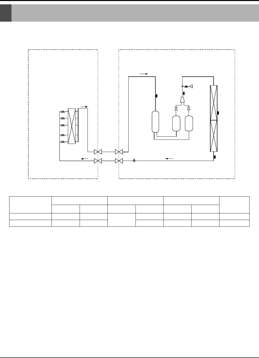
Refrigerant Cycle Diagrams
1. Cooling Only Models
INDOOR UNIT
H/EX
LIQUID SIDE
Gas Side
GAS SIDE
Capillary Tube
OUTDOOR UNIT
Thermistor
(Air)
E.E.V.
Accumulator
Heat
Exchanger
Check
Valve
Constant
Compressor 1
Constant
Compressor 2
Check
Valve
Thermistor
Thermistor
High
pressure
S/W
Thermistor
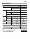
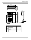
24k
34k
Gas Liquid Rated Max. Rated Max.
Pipe Size(Diameter:Ø) inch
Piping length (ft.) Elevation (ft.)
Capacity
Additional
Refrigerant
(oz/ft)
1/4
1/4
1/2
5/8
25
100
115
50
66
16
16
Refrigerant Cycle Diagrams
0.22
0.32