


compressor (HERM) terminal. A satisfactory capacitor will cause a deflection on the pointer,
then gradually move back to infinity.
4. Reverse the leads of the probe and momentarily touch the capacitor terminals. The
deflection of the pointer should be two times that of the first check if the capacitor is good.
5. Repeat steps 3 and 4 to check fan motor capacitor.
NOTE: A shorted capacitor will indicate a low resistance and the pointer will move to the "0"
end of the scale and remain there as long as the probes are connected.
An open capacitor will show no movement of the pointer when placed across the
terminals of the capacitor.
6.4 THERMOSTAT ADJUSTMENT
No attempt should be made to adjust thermostat. Due to the sensitivity of the internal
mechanism and the sophisticated equipment required to check the calibration, it is suggested
that the thermostat be replaced rather than calibrated. Thermostat bulb must be straight to
insure proper performance.
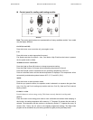
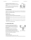
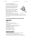
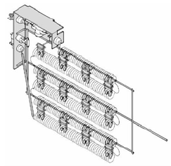
6.5 HEATING ELEMENT - See Figure 6
All electric heater models are equipped with a heating element.
The heating element contains a fuse link and a heater limit
switch. The fuse link is in series with the power supply and
will open and interrupt the power when the temperature
reaches 183.2°F (84°C) or 199.4°F (93°C) depending on series
model, or a short circuit occurs in the heating element.
Once the fuse link separates, a new fuse link must
be installed. NOTE: Always replace with the exact replacement.
The heater element has a high limit control. This control is a
bimetal thermostat mounted in the top of the heating element. Figure 6: Heating element
Should the fan motor fail or filter become clogged, the high limit
control will open and interrupt power to the heater before reaching an unsafe temperature
condition.
The control is designed to open at 104°F (40°C). Test continuity below 104°F (40°C). and for
open above 104°F (40°C)..
Press the “Mode” button, select “Heat” mode, to bring on the heating element and turn off the
compressor. The room temperature sensor will then control the cycling of the element when
the selected indoor temperature is reached.
Testing of the elements can be done using an ohmmeter across the terminals after the
connecting wires have been removed. A cold resistance reading of approximately 10.2 ohms
for the 4.7 KW heater should be registered.
Service Manual
Room Air Conditioner with R-410A
Heat Controller, Inc.
12