


—12—
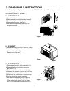
2.4 REFRIGERATION CYCLE
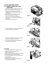
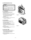
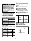
2.4.1 CONDENSER
1. Remove the cabinet. (Refer to section 2.1.2)
2. Remove the brace and the shroud cover.
(Refer to section 2.2.1)
3. Remove the 5 screws which fasten the condenser.
4. After discharging the refrigerant completely into a
Freon
TM
Recovery System, unbraze the
interconnecting tube at the condenser
connections.
5. Remove the condenser.
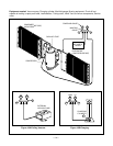
6. Re-install the components by referring to the notes
– on pages 13-14. (See Fig. 16)
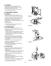
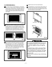
2.4.2 EVAPORATOR
1. Remove the cabinet. (Refer to section 2.1.2)
2. Discharge the refrigerant completely – into a
Freon
TM
Recovery System.
3. Remove the 2 screws which fasten the evaporator
at the left side and the right side.
4. Move the evaporator sideward carefully and then
unbraze the interconnecting tube at the evaporator
connectors.
5. Remove the evaporator.
6. Re-install the components by referring to the notes
– on pages 13-14. (See Fig. 17)
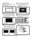
2.4.3 CAPILLARY TUBE
1. Remove the cabinet. (Refer to section 2.1.2)
2. After discharging the refrigerant completely – into
a Freon
TM
Recovery System, unbraze the
interconnecting tube at the capillary tube.
3. Remove the capillary tube.
4. Re-install the components by referring to the notes
– on page 13-14.
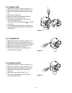
Figure 16
Figure 17
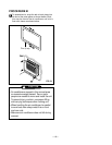
Discharge the refrigerant system using a Freon
TM
Recovery System.
If there is no valve to attach the recovery system,
install one (such as a WATCO A-1) before
venting the Freon
TM
. Leave the valve in place
after servicing the system.
CAUTION