


VI. INSTALLATION
A
. GENERAL
1. PRE-INSTALLATION CHECK-POINTS
Before attempting any installation, the following points
should be carefully considered:
a. Structural strength of supporting members.
(rooftop installation)
b. Clearances and provision for servicing.
c
. Power supply and wiring.
d. Air duct connections.
e. Drain facilities and connections.
f. Location for minimum noise.
2. LOCATION
These units are designed for outdoor installations. They
can be mounted on a slab or rooftop. They are not to be
installed within any part of a structure such as an attic,
crawl space, closet, or any other place where condenser
air flow is restricted or other than outdoor ambient condi-
tions prevail. Since the application of the units is of the
outdoor type, it is important to consult your local code
authorities at the time the first installation is made.
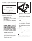
B. OUTSIDE SLAB INSTALLATION (Typical outdoor slab
installations are shown in Figures 6 and 7.)
1. Select a location where external water drainage cannot
collect around the unit.
2. Provide a level concrete slab extending 3" [76.2 mm]
beyond all four sides of the unit. The slab should be suf-
ficient above grade to prevent ground water from enter-
ing the unit. IMPORTANT: To prevent transmission of
noise or vib ration, slab should not be connected to
building structure.
3. The location of the unit should be such as to provide
proper access for inspection and servicing.
4. Locate unit where operating sounds will not disturb
owner or neighbors.
5. Locate unit so roof runoff water does not pour directly on
the unit. Provide gutter or other shielding at roof level.
Do not locate unit in an area where excessive snow drift-
ing may occur or accumulate.
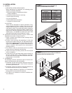
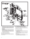
C. CLEARANCES
The following minimum clearances must be observed for
proper unit performance and serviceability.
1. Provide 48" [1219.2 mm] minimum clearance at the front
of the unit. Provide 18" [457.2 mm] minimum clearance
at all other sides of the unit.
2. Provide 60" [1524 mm] minimum clearance between top
of unit and maximum 3 foot [.91 m] overhang.
3. Unit is design certified for application on combustible
flooring with 0" [0 mm] minimum clearance.
4. See Figure 6 for illustration of minimum installation-ser-
vice clearances.
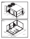
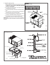
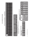
FIGURE 6
O
UTSIDE SLAB INSTALLATION, BASEMENT OR
C
RAWL SPACE DISTRIBUTION SYSTEM
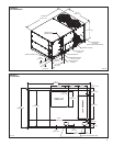
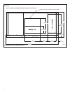
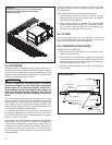
FIGURE 7
OUTSIDE SLAB INSTALLATION, CLOSET DISTRIBUTION
SYSTEM. SLAB FLOOR CONSTRUCTION
A0739-03
A
0741-03
Recommended
Clearance
Location
48” [1219.2 mm] A - Front
18” [457.2 mm] B - Condenser Coil
18” [457.2 mm] C - Duct Side
18”* [457.2 mm] D - Evaporator End
60” [1524 mm] E - Above
*Without Economizer. 48” [1219.2 mm] With
*Economizer
12