


27
Heat & Glo • SL-750TRS-IPI-E, SL-550TRS-IPI-E, SL-350TRS-IPI • 2120-901 Rev. G • 11/08
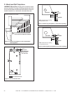
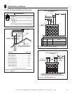
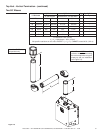
Figure 7.4
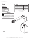
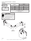
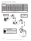
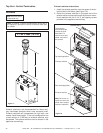
F. Vent Diagrams
Top Vent - Horizontal Termination Venting
V Minimum
H
1
Maximum
SL-350TRS-IPI SL-550, SL-750TRS-E
90º Elbow 1-1/2 ft. 457 mm 1 ft. 305 mm
1/2 ft.* 152 mm 2 ft. 610 mm 2 ft. 610 mm
1-1/2 ft.* 457 mm 3 ft. 914 mm 3 ft. 914 mm
2-1/2 ft.* 762 mm 5 ft. 1-1/2 m 5 ft. 1-1/2 m
3-1/2 ft. 1.1 m 7 ft. 2.1 m 7 ft. 2.1 m
4-1/2 ft. 1.4 m 15 ft. 4.6 m 15 ft. 4.6 m
H
1
Maximum= 15 ft. (4.6 m)
V
1
+ H
1
Maximum= 40 ft. (12.2 m)
* See warning below
Note: Use SLP Series
components only.
Note: There MUST be a 25%
reduction in total H when using
fl ex vent except when using the
simple up and out installation
(see Figure 5.3).
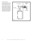
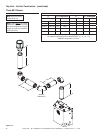
One Elbow
Fire Risk.
• When using SLP-HRC-SS and SLP-HRC-ZC-
SS termination caps on top vented fi replaces,
a one foot minimum vertical vent section is
required before installing fi rst elbow.
• When using DVP-TB1 termination cap on top vented
fi replaces, a three foot minimum vertical vent section is
required before installing fi rst elbow.
H
1
V
1
WARNING *