


Hearth & Home Technologies Inc. • Plug & Play • 4050-317 Rev A • 04/08
4
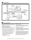
The Optional Wall Switch 4050-309 contains two single pole switches. (LEVITON 5634 Series or equal)
The Optional Wall Thermostat is a low voltage mechanical type. (Columbus Electric RK120EAA or equal)
Maximum run distance is 30 ft. (9.14 m) with 20 gauge solid copper low voltage thermostat wire. Connect per the elec-
trical wiring diagram on page 7.
WARNING! Do NOT connect the optional low voltage switch and/or thermostat to 120 volt branch circuit.
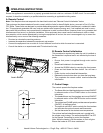
E. Cord Electrical Connection
WARNING! Electrical wiring must comply with local
building codes and other applicable regulations to
reduce the risk of fi re, electrical shock and injury.
D. Electrical Specifi cations
Voltage . . . . . . . . . . . . . . . . . . . . . . 120 V AC, 60 Hz
Total Amps . . . . . . . . . . . . . . . . . . . . . . . . . .9.6 AMP
Total Watts . . . . . . . . . . . . . . . . . . . . . . . 1050 Watts
Heater Rating: . . . . . . . . . . . .1000 Watts/3415 BTU
B. Locating Your Electric Fireplace
Your new electric fi replace may be installed virtually anywhere in your home. However, when choosing a location ensure
that the general instructions are followed. For best results, install out of direct sunlight.
Carefully remove packaging from the unit. The front screen is held in place with four Phillips head screws. To remove the
screen, extract the screws. Grasp the screen frame and pull out.
WARNING! Do NOT use this appliance if any part has been under water. Immediately call a qualifi ed service techni-
cian to inspect and to replace any part of the electrical system if necessary.
A. Unpacking the Unit
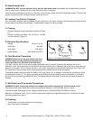
Figure 1.1 Cord Electrical Connection
Grounding
Pin
Metal Screw
Cover of Grounded
Outlet Box
Grounding
Head
CBA
F. Wall Switch and Thermostat Connections
A 15 AMP, 120 Volt, 60 Hz circuit with a properly grounded outlet is required. Preferably the fi replace will be on a
dedicated circuit. Other appliances on the same circuit may cause the circuit breaker to trip or the fuse to blow when the
heater is in operation. The unit comes with a 6 ft. (152.4 mm) long three wire 16 AWG IEC-320 power cord. Plug in the
IEC connector to the rear upper corner of the appliance then connect the cord to the wall socket.
The fi replace power cord has a three pin NEMA-5-15P plug (Figure 1A). An adapter is available for connecting to a two-
slot receptacle (Figure 1C). The green grounding wire extending from the adapter must be connected to a permanent
ground such as a properly grounded outlet box. The adapter should not be used if a three slot grounded receptacle is
available.
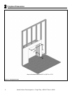
C. Framing
• Choose a fi replace location and frame as shown in Figure
2.1.
• Provide a properly gounded, 120 volt, 60 Hz, 15 AMP
circuit as shown in Figure 2.1.
G. Finishing
• The fi replace can now be positioned in the opening.
• Level it with shims if necessary.