


36
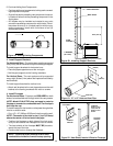
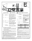
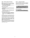
For Intermittent Pilot Ignition (IPI) Wiring
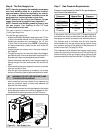
Appliance Requirements
This appliance requires that 110-120 VAC be wired to the
junction box. Maintain correct polarity when wiring the junc-
tion box.
Operation using Battery Power
This fireplace has an optional battery operation. The sys-
tem is fully functional with the use of two “D” size batteries
without ordinary 110-120 VAC power.
Wiring to the battery pack should be left disconnected in
order to conserve battery life. In the case of a loss of power,
simply connect red and black wire leads to activate battery
power (connect red to red, black to black). The fireplace
can be used as necessary. Once power (110 VAC) is re-
stored, disconnect red and black wire leads to extend bat-
tery life.
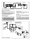
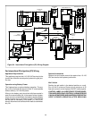
Figure 34. Intermittent Pilot Ignition (IPI) Wiring Diagram
Optional Accessories
Optional fan and remote control kits require that 110-120
VAC be wired to the fireplace junction box.
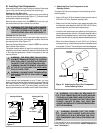
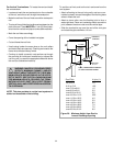
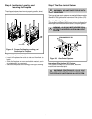
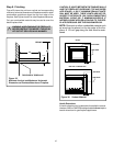
Wall Switch
Position the wall switch in the desired position on a wall.
Run 16 A.W.G. minimum Romex wire a maximum of 25
feet and connect it to the fireplace ON/OFF switch pigtails.
CAUTION: LABEL ALL WIRES PRIOR TO DISCONNEC-
TION WHEN SERVICING CONTROLS. WIRING ERRORS
CAN CAUSE IMPROPER AND DANGEROUS OPERATION.
VERIFY PROPER OPERATION AFTER SERVICING.
WALL SWITCH
R
E
D
B
L
K
IGNITION MODULE 3 VAC
TRANSFORMER
3 VAC
BRN
BRN
GRN
O
R
G
VALVE
OPTIONAL
BATTERY BACKUP
JUNCTION BOX
120 VAC
OPTIONAL
REMOTE
GROUND TO
FIREPLACE
CHASSIS
FAN
REM
REM
FAN
JUNCTION BOX
120 VAC
ORG
WHT
I
S
INTERMITTENT PILOT IGNITOR
R
E
D
B
L
K
IGNITION
MODULE
(3V)
VALVE
ON/OFF
WALL SWITCH
LOW VOLTAGE
LOW VOLTAGE
PLUG-IN
3V TRANSFORMER
NEUTRAL HOT
GROUND
FLAME SPARKER/
SENSOR
OPTIONAL
BATTERY
BACK-UP
REMOTE
CONTROL
SEE NOTE 1
SEE NOTE 1
FAN OUTLET RECEPTACLE
(NO FAN OPTION)