


Heatilator • Novus NDV Series • 4055-187 Rev F • 06/0840
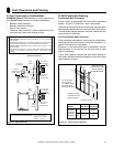
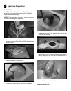
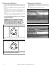
B. Assemble Vent Sections (SLP Pipe Only)
To attach the fi rst vent component to the starting collars of
the appliance
• Attach an SLP-DVP24 adapter to the starting collar of
the appliance.
• Lock the vent components into place by sliding the pipe
section onto the collar.
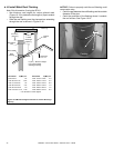
• Align the seam of the pipe and seam of collar to allow
engagement. Rotate the vent component to lock into
place. Use this procedure for all vent components. See
Figure 10.5.
• Slide the gasket over the fi rst vent section and place it
fl ush to the appliance. This will prevent cold air infi ltration.
High temperature caulk may be used to hold the part in
place.
• Continue adding vent components, locking each
succeeding component into place.
• Ensure that each succeeding vent component is securely
fi tted and locked into the preceding component.
1 - Align Seams
2 - Rotate
Figure 10.5 Adding Venting Components
WARNING! Risk of Fire or Explosion! DO NOT break
silicone seals on slip sections. Use care when removing
termination cap from slip pipe. If slip section seals are bro-
ken during removal of the termination cap, vent may leak.
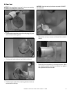
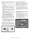
Commercial, Multi-family (Multi-level exceeding
two stories), or High-Rise Applications
For Installation into a commercial, multi-family (multi-level
exceeding two stories) or high-rise applications: All outer
pipe joints must be sealed with high temperature silicone,
including the slip section that connects directly to the hori-
zontal termination cap.
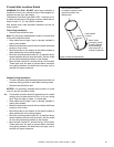
• Apply a bead of silicone sealant inside the female outer
pipe joint prior to joining sections. See Figure 10.1
• Only outer pipes need to be sealed. All unit collar, pipe,
slip section, elbow and cap outer fl ues shall be sealed
in this manner, unless otherwise stated.
(outer)
(inner)
Cut from this end
Cut from this end
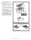
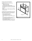
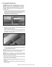
C. Assemble MI Sections (DVP only)
WARNING! Risk of Fire or Asphyxiation! Overlap pipe
sections at least 1 1/2 in. (38 mm). Secure MI sections
with three screws which must not exceed 1/2 in. (13 mm)
in length. Pipe could separate if not properly joined.
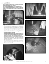
MI (Minimum Installation) sections are non-unitized so
that they can be cut to a specifi c length.
• Cut sections to length from the non-expanded end (see
Figure 10.6). Maintain 1-1/2 in. (38 mm) overlap.
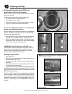
• Connect the expanded end of the MI inner fl ue with the
inner fl ue of the adjacent pipe section and secure with
three screws.
Figure 10.6 MI Sections
CAUTION! Risk of Fire! The expanded portion of the MI
inner fl ue must overlap completely with the unexpanded
end of the adjacent pipe section.
• Connect the cut end of the MI outer flue with the
expanded end of the outer fl ue of the adjacent pipe
section and secure with three screws.
• It is acceptable to use screws no longer than 1/2 in. (13
mm) to hold outer pipe sections together. If predrilling
holes, DO NOT penetrate inner pipe.
• Continue adding pipe sections as necessary following
instructions in “Assemble Pipe Sections.”
ÎÎ