


28
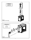
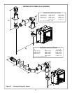
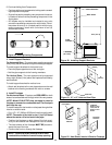
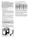
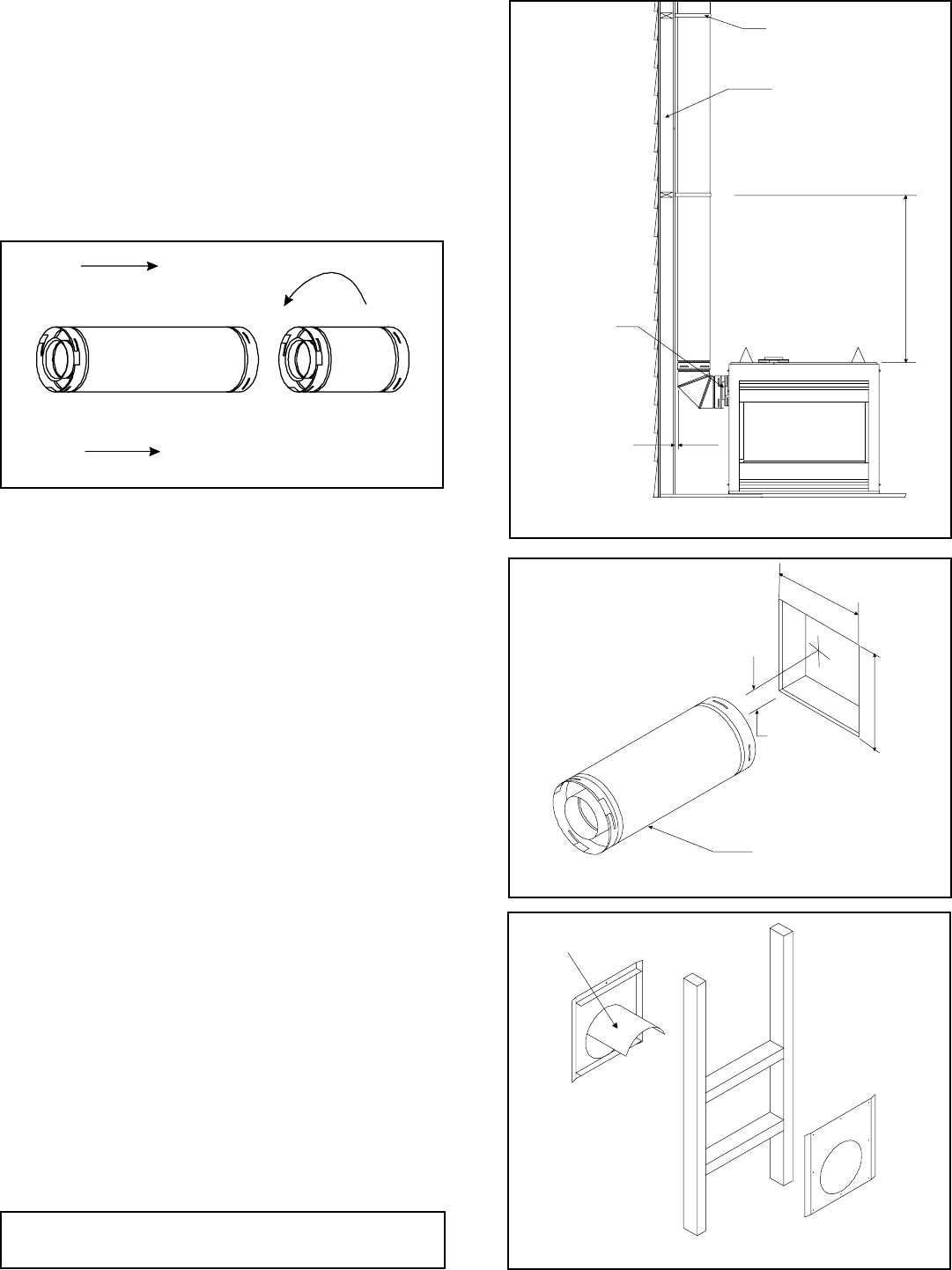
For Vertical Runs - The vent system must be supported
every eight (8) feet (2.4m) above the fireplace flue outlet by
wall brackets.
To install support brackets for vertical runs:
• Attach wall brackets to the vent pipe and secure the wall
bracket to the framing members with nails or screws.
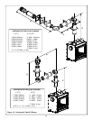
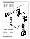
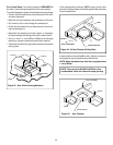
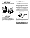
4. Install Firestops
For Horizontal Runs - Firestops are REQUIRED on both
sides of a combustible wall through which the vent passes.
NOTE: Model DVK-01TRD does not need an exterior
firestop on an exterior combustible wall. The firestop is
built into the cap.
To install firestops for horizontal runs that pass through either
interior or exterior walls:
• Cut a 12” x 12” (305mm X 305mm) hole through the wall.
NOTE: The center of the hole is one (1) inch (25.4mm)
above the center of the horizontal vent pipe.
• Position the firestops on both sides of the hole previ-
ously cut and secure the firestops with nails or screws.
• The heat shields of the firestops MUST BE placed to-
wards the top of the hole.
• Continue the vent run through the firestops.
Figure 21. 12" x 12" Hole and Vent Pipe
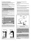
Figure 22. Heat Shield, Interior & Exterior Firestops
V
ENT PIPE
1" (25.4 mm)
12"
(305mm)
12"
(305mm)
TRIM HEAT
SHIELD IF TOO
LONG, ADD TO
SHIELD IF TOO
SHORT
EXTERIOR
FIRESTOP
INTERIOR
FIRESTOP
HEAT SHIELD
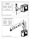
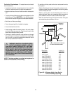
3. Install Support Brackets
For Horizontal Runs - The vent system must be supported
every five (5) feet of horizontal run by a horizontal pipe support.
To install support brackets for horizontal runs:
• Place the pipe supports around the vent pipe.
• Nail the pipe supports to the framing members.
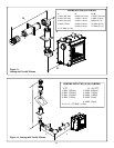
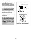
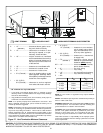
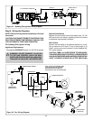
Figure 19. Adding Venting Components
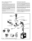
2. Continue Adding Vent Components
• Continue adding vent components, locking each succeed-
ing component into place.
• Ensure that each succeeding vent component is secure-
ly fitted and locked into the preceding component in the
vent system.
• 90° elbows may be installed and rotated to any point
around the preceding component’s vertical axis. If an el-
bow does not end up in a locked position with the pre-
ceding component, attach with a minimum of two (2)
sheet metal screws.
Figure 20. Installing Support Brackets
FLUE
OUTLET
1 INCH MIN.
(25.4 mm)
8 FT. (2.4 m)
WALL STUD
WALL BRACKET
NOTE: There must be NO INSULATION or other
combustibles inside the framed firestop opening.