


Hearth & Home Technologies • Grand Oak Gas Log Sets • 4004-299 Rev H • 05/08
6
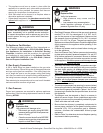
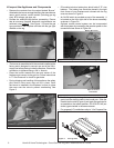
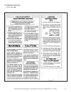
H. Inspect the Appliance and Components
• Remove the contents from the carton labeled “Burner”.
Attached to the burner are tags identifying the manufacturer
name, serial number, model number (including gas log
size), BTU ratings, gas type, etc.
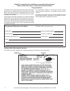
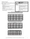
• Review the attached tags before proceeding. Ensure
that all minimum replace dimension requirements are
achieved using Table 3 . See Figure 1. Ensure the gas
type provided in the replace coincide with the gas type
marked on the tag.
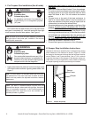
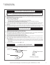
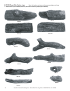
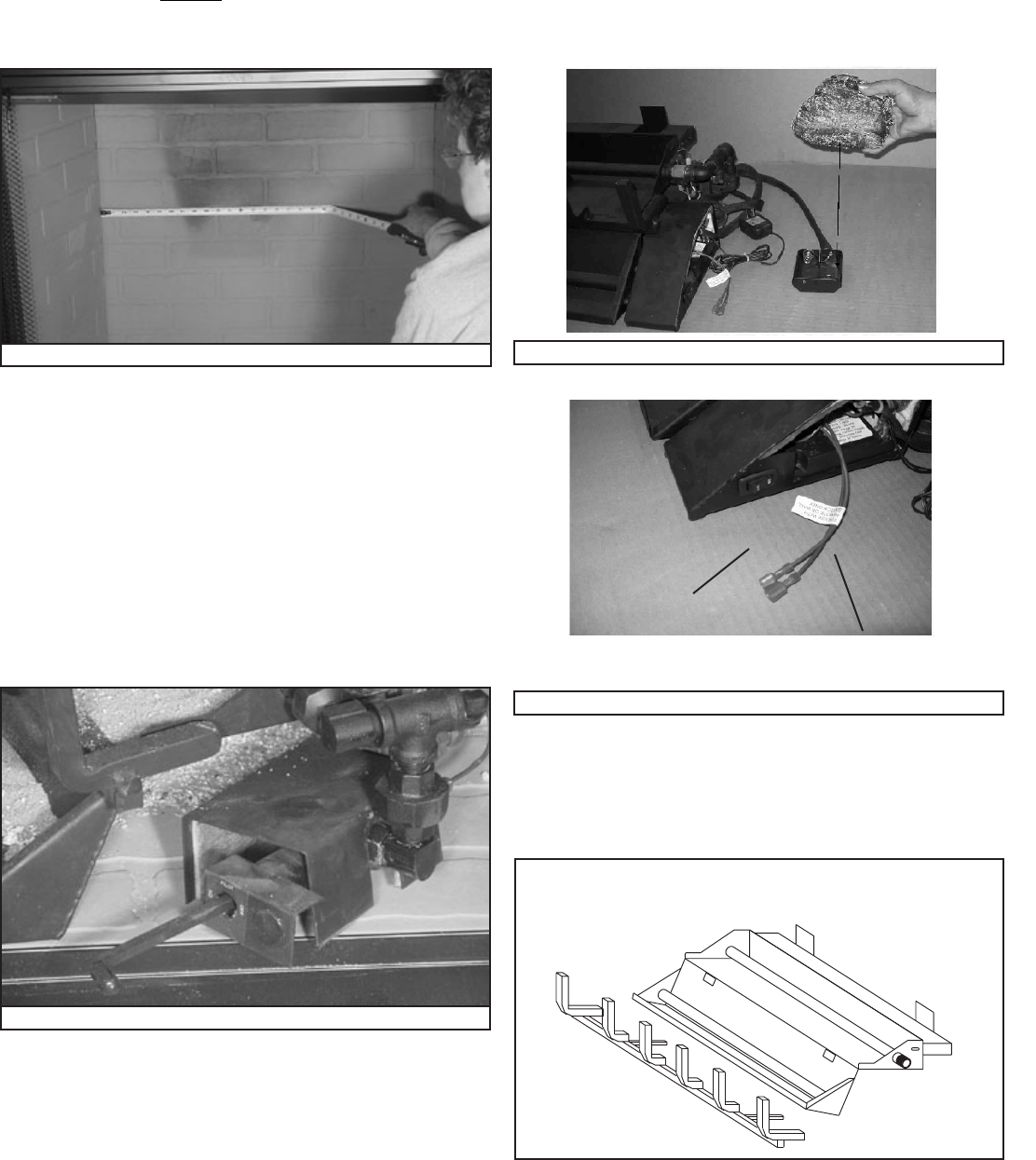
Figure 4 Placing Grate
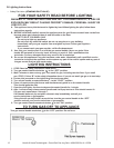
Figure 2 Valve Cover (Safety Pilot)
Figure 1 Measure Firebox
• The burner is assembled with the controls installed at the
factory and is designed to connect one end of the 3/8 in.
supply line before placing inside the replace. Ensure the
connection is tightened using a 3/4 in. wrench.
• Place the burner towards the rear and center of the
replace and connect to the gas line. Follow instructions
in “F. Gas Pressure” to check for gas leaks.
• During shipping and handling of this appliance the safety
pilot control valve cover may not be in place. Once
the burner is installed in the replace, be sure to place
the cover over the valve to prevent overheating. See
Figure 2.
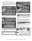
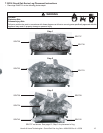
• IPI models include a battery box which holds 2 “D” size
batterys. The battery box should be placed in the right
front corner of your replace and covered with the log
cover as shown in Figure 3.
Figure 3A Control Box for IPI
Battery Box Cover
Battery Box
Figure 3 Battery Box and Cover (for IPI units only)
On/Off Switch
Optional Remote
Connection
• An On/Off switch is provided as part of the assembly. It
is located on the front right side of the burner assembly
as shown in Figure 3A.
• Optional remote control system can be incorporated
with this system by connecting the remote system to the
connection wires shown in Figure 3A.
• Install the grate by placing the inserts (attached to the
grate) into the slots provided in the burner pan. Slide the
inserts into the slots (Figure 4) and push the grate as far
as possible to the locked position. GO 35 & GO 40 (not
shown) grate installs in the same manner.
• For propane (LP) installations skip to “J for Propane Gas
Installation”.